V6-i VRF 50/60Hz
64
Midea
V6
-i
Series S
er
vice M
anual
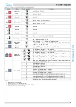
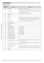
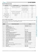
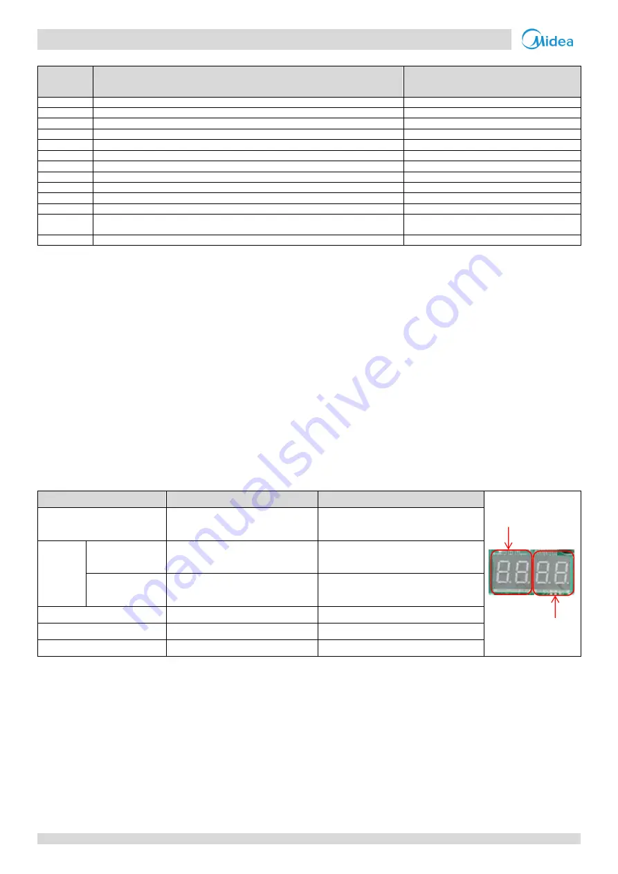
Table 5-2.5:
System check (continued)
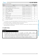
DSP1
content
Parameters displayed on DSP2
Remarks
34.--
Reserved
35.--
Reserved
36.--
DC voltage A
Actual value = value displayed × 10
37.--
DC voltage B
Actual value = value displayed × 10
38.--
Reserved
39.--
Address of VIP indoor unit
40.--
Reserved
41.--
Reserved
42.--
Refrigerant quantity
Refer to Note 8
43.--
Reserved
44.--
Power mode
Refer to Note 9
45.--
Most recent error or protection code
“--“ is displayed if no error or protection events
have occurred since start-up
-- --
--
End
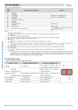
Notes:
1. Outdoor unit capacity setting:
0: 8HP; 1: 10HP; 2: 12HP; 3: 14HP; 4: 16HP; 5: 18HP; 6: 20HP; 7: 22HP; 8: 24HP; 9: 26HP; A: 28HP; B: 30HP; C: 32HP.
2. Operating mode:
0: off; 2: cooling; 3: heating; 4: forced cooling.
3. The fan speed index is related to the fan speed in rpm and can take any integer value in the range 1 (slowest) to 35 (fastest).
4. 480P: steps = value displayed × 4; 3000P: steps = value displayed × 24.
5. Priority mode:
0: auto priority; 1: cooling priority; 2: VIP priority or voting priority; 3: heating only; 4: cooling only.
6. Silent mode:
0: night silent time 6h/10h; 1: night silent time 6h/12h; 2: night silent time 8h/10h; 3: night silent time 8h/12h; 4: no silent mode; 5: silent mode 1; 6:
silent mode 2; 7: silent mode 3; 8: super silent mode 1; 9: super silent mode 2; 10: super silent mode 3; 11: super silent mode 4.
7. Static pressure mode:
0: standard static pressure; 1: low static pressure; 2: medium static pressure; 3: high static pressure; 4: super high static pressure.
8. Refrigerant quantity:
0: normal; 1: slightly excessive; 2: significantly excessive; 3: slightly insufficient; 4: significantly insufficient; 5: critically insufficient.
9. Power mode:
0: 100% capacity output; 1: 90% capacity output; 2: 80% capacity output; 3: 70% capacity output; 4: 60% capacity output; 5: 50% capacity output; 6:
40% capacity output; 10: auto power save mode, 100% capacity output; 11: auto power save mode, 90% capacity output; 12: auto power save
mode, 80% capacity output; 13: auto power save mode, 70% capacity output; 14: auto power save mode, 60% capacity output; 15: auto power save
mode, 50% capacity output; 16: auto power save mode, 40% capacity output;
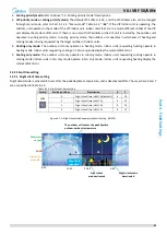
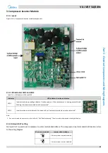
Digital display output
2.2.5
Table 5-2.6: Digital display output in different operating states
Outdoor unit state
Parameters displayed on DSP1
Parameters displayed on DSP2
Standby
Unit's address
The number of indoor units in
communication with the outdoor unit
Normal
operation
For single
compressor units
--
Running speed of the compressor in
rotations per second
For dual
compressor units
Running speed of compressor B in
rotations per second
Running speed of compressor A in
rotations per second
Error or protection
-- or placeholder
Error or protection code
In menu mode
Refer to Table 5-2.3
Refer to Table 5-2.3
System check
Refer to Table 5-2.5
Refer to Table 5-2.5
DSP1
DSP2

