V6-i VRF 50/60Hz
95
P
art
6
- Di
agno
si
s and
Tr
ou
bles
ho
o
ting
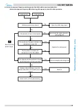
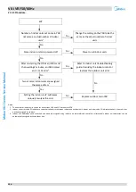
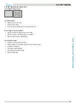
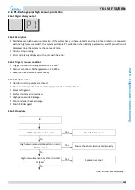
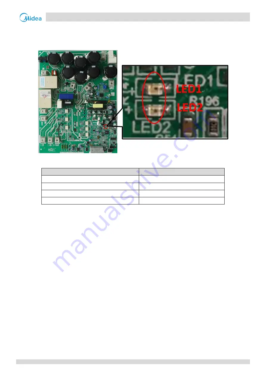
The specific error codes xL0, xL1, xL2 and xL4 can also be obtained from the inverter module LED indicators. If an inverter
module error has occurred, LED2 is continuously on and LED1 flashes.
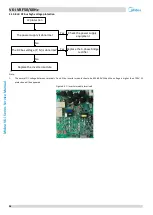
Figure 6-2.4: LED indicators LED1 and LED2 on inverter module
Table 5-3.2: Errors indicated on LED1
LED1 flashing pattern
Corresponding error
Flashes 8 times and stops for 1 second, then repeats
xL0 - Inverter module protection
Flashes 9 times and stops for 1 second, then repeats
xL1 - DC bus low voltage protection
Flashes 10 times and stops for 1 second, then repeats
xL2 - DC bus high voltage protection
Flashes 12 times and stops for 1 second, then repeats
xL4 - MCE error


