background image

22

INSTALLATION  INSTRUCTIONS

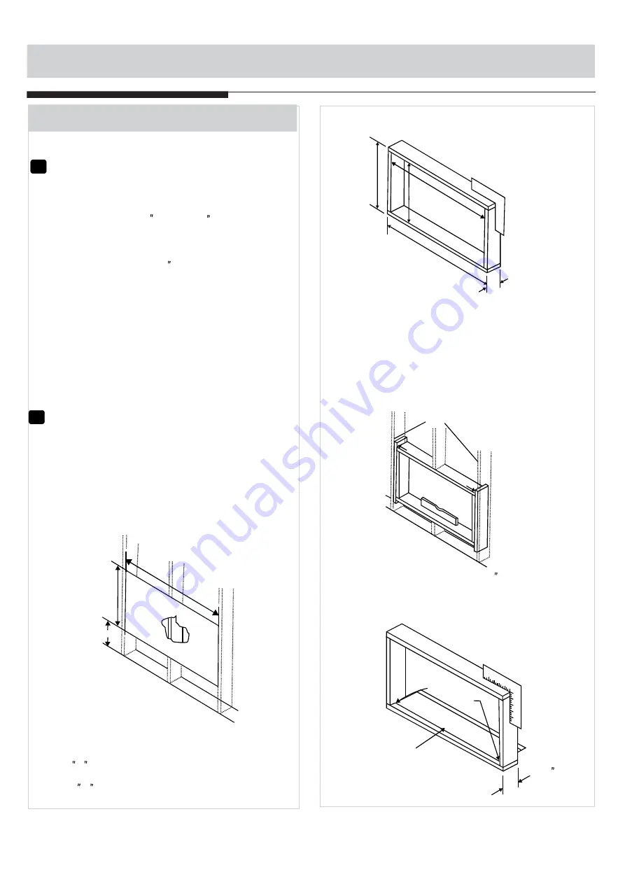
NAIL SPACERS
  TO STUDS

LEVEL

Fig.3

NOTE: 

If wall thickness is 8-1/2  or more, add

aluminum flashing over bottom of frame opening
to assure no water can enter area between inner
and outer wall.

Caulks
Required

Aluminum Flashing
Over Bottom Of Frame

Over 
8-1/2 

Fig.4

4. Build a wooden frame with the INSIDE dimen-
    sions of your model listed above. (Remember to 
    measure twice). Frame depth should be the
    same as wall  thickness. Fill in the space from
    the opening to the studs with wood spacers,
   as shown.
5. Nail frame to spacers to spacers with front 
    flush with drywall.

Inside Frame Height: 18-7/8"(47.9cm) or18"  (45.7cm)
Inside Frame Width:   26-3/4"(67.9cm) or 23-7/8"(60.6cm)

Fg.2

Frame

Height

Inside

Frame

Y

Inside

Width

Up to 8-1/2"

B.Thru-The-Wall Installation

1

Select Wall Location

The air conditioner has a slide-out chassis, so
that it can be installed through an outside wall
as specified below: 
Max. Wall thickness: 12      or      10

 Side louvers must never be blocked.

 All parts needed for Thru-The-Wall Install-

ation are provided, except a wood frame, shims, 
and 10 wood screws(#10-1  long minimum). 
Select a wall surface that:
1. does not support major structural loads such
    as the frame construction at ends of windows,
    and under truss-bearing points, etc.

IMPORTANT:
NOTE:

NOTE: Consult local building codes prior to 
installation or a qualified carpenter.

2

Prepare Wall

1. Prepare wall in frame construction (including
    brick and stucco veneer). Working from inside
    the room, find wall stud nearest the center of 
    area where air conditioner will be installed 
    (by sounding wall or by magnetically finding
     nails).

2. Cut or knock out a hole on each side of center stud.
3. Measure between inside edges of every other
    stud as shown in Fig.1.

Fig.1

3-3/8" MIN
 (8.6 cm)

Carefully measure and cut an opening with the
following dimensions depending on your model.
See Fig.1 and Fig.2. 
WIDTH  X = inside model width plus twice the
thickness of framing material used.
HEIGHT  Y   = inside model height plus twice the
thickness of framing material used.

2. does not have plumbing or wiring inside.
3. is near existing electrical outlets or where 
    another outlet can be installed.
4. is not blocked to the area to be cooled.
5. allows unblocked airflow from rear sides and
    end(outside) of installed air conditioner.

Summary of Contents for MW06DRWBA1RCM

Page 1: ...210 285 80g...

Page 2: ...al carefully and keep it for future reference WINDOW TYPE ROOM AIR CONDITIONER TABLE OF CONTENTS Installation Instructions 24 10 23 Normal Sounds Important Safety Instructions 1 9 Troubleshooting Tips...

Page 3: ...eat generation excess It may cause electric shock or fire due to heat generation Incorrect grounding may cause electric shock It may cause fire and electric shock It may cause fire It may cause explos...

Page 4: ...ters maycause failure It contains contaminants and could make you sick Stop operation and close the window in storm or hurricane Do not use strong detergent such as wax or thinner but use a soft cloth...

Page 5: ...he window is a triple track type with a screen panel included remove the screen completely before installation Be sure the air conditioner has been securely and correctly installed according to the in...

Page 6: ...of the person competent in the use of flammable refrigerants DO NOT modify the length of the power cord or use an extension cord to power the unit DO NOT share a single outlet with other electrical ap...

Page 7: ...hecks to the area Prior to beginning work on systems containing flammable refrigerants safety checks are necessary to ensure that the risk of ignition is minimised For repair to the refrigerating syst...

Page 8: ...sence of refrigerant Marking to the equipment continues to be visible and legible Markings and signs that are illegible shall be corrected Refrigeration pipe or components are installed in a position...

Page 9: ...not be used The following leak detection methods are deemed acceptable for systems containing flammable refrigerants Electronic leak detectors shall be used to detect flammable refrigerants but the s...

Page 10: ...ressure tested with OFN The system shall be leak tested on completion of charging but prior to commissioning A follow up leak test shall be carried out prior to leaving the site Before carrying out th...

Page 11: ...if possible cooled before recovery occurs The recovery equipment shall be in good working order with a set of instructions concerning the equipment that is at hand and shall be suitable for the recov...

Page 12: ...this manual are for explanation purpose only The air conditioner you have may be slightly different The actual shape shall prevail NOTE INSTALLATION INSTRUCTIONS NOTE The unit you purchased may be loo...

Page 13: ...in these instructions when installing this air conditioner BEFORE YOU BEGIN Do not under any circumstances cut or remove the third ground prong from the power cord CAUTION Do not change the plug on t...

Page 14: ...h models only Fig C NOTE The top rail hardware and the Fig A Fig B and Fig C are not applicable to the units more than 10000Btu h Before installing unit the top rail must be assembled on the unit For...

Page 15: ...against the window sill Fig 5A and Fig 5B Carefully close the window behind the top rail of the unit Fig 5A If storm window blocks AC see Fig 11 NOTE Top Rail Bottom Rail Top left Top right Fig 4 Woo...

Page 16: ...frame lock and frame extensions into the windows sash as shown Fig 8B Fig 8A Fig 8B C To secure lower sash in place attach right angle sash lock with 3 4 19mm or 1 screw as shown Fig 9 2 12 7mm Fig 9...

Page 17: ...irm grip on air conditioner raise sash and carefully remove Be carefully not to spill any remaining water while lifting unit from window Store parts WITH air conditioner Board thickness as required fo...

Page 18: ...ils Save Carton and these Installation Instructions for future reference The carton is the best way to store unit during winter or when not in use NOTE Preliminary Instructions Do the following before...

Page 19: ...nch Long Flat Head Bolt and Locknut Sill Angle Bracket Long hex head locking screw for top angle side retainer 5 16 inch Long 2 ea 7 1 4ea 2ea 2 10 Foam insert 2 Window sash seal foam 1 A Window Mount...

Page 20: ...tigh ten Allow leg to slide freely Screws will be tightened after section 6 4 Place Cabinet in window 1 Open window and mark center of window inner sill as shown Fig 11 2 Place cabinet in window with...

Page 21: ...ise window to expose filler panel locking screws Loosen screws so filler panels slide easily 2 Extend panels to fill window opening completely Tighten locking screws on top Fig 17 3 Install support br...

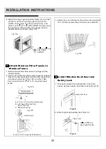
Page 22: ...gh the hole in the top leg of each window filler panel and into the window sash Fig 18A and Fig 18B Connect with one 3 4 or 1 2 long hex head screw 8 1 Trim sash seal to fit window width Insert into s...

Page 23: ...In order to minimize air leaks and ensure optimal insulation it is necessary to install the included R1 hardware to the side curtain Follow the instructions below Step 1 After the unit is installed t...

Page 24: ...d except a wood frame shims and 10 wood screws 10 1 long minimum Select a wall surface that 1 does not support major structural loads such as the frame construction at ends of windows and under truss...

Page 25: ...versized to eliminate distortion See Fig 8 Remember to maintain proper slope as described in Step 3 Fig 8 OPTIONAL NOTE Caulking and installation of trim on interior wall may be done You can buy wood...

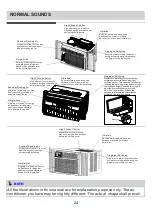
Page 26: ...may be heard due to refrigerant passing through evaporator during normal operation Pinging or Switching Droplets of water hitting condenser during normal operation may cause pinging or switching soun...

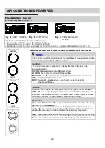
Page 27: ...ctional Louvers Lever Air Direction The louvers will allow you to direct the air flow Left or Right throughout the room as needed Move the Levers from side to side until the desired Left Right directi...

Page 28: ...kwise for higher cool settings Higher cool settings will provide lower room temperature Rotate the thermostat selector counter clockwise for lower cool settings Lower cool settings will provide higher...

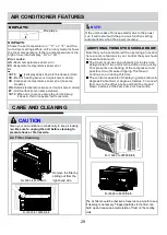
Page 29: ...ROL OPERATING INSTRUCTIONS Auto Low Med High Follow Me Auto Cool Dry Fan Mode Fan Energy Saver Check Filter On Off Sleep Timer Ion TEMP TIMER Low Auto Med High TEMP TIMER Auto Cool Dry Fan Fan Mode On...

Page 30: ...the remote control towards the unit and press the Follow Me button T If the unit does not receive the Follow Me signal during any 7 minutes interval the unit will beep to indicate the Follow Me mode...

Page 31: ...w Be sure to unplug the unit before cleaning to prevent shock or fire hazards Air Filter Cleaning The air filter should be checked at least once a month to see if cleaning is necessary Trapped particl...

Page 32: ...cted Push plug firmly into wall outlet House fuse blown or circuit breaker tripped Replace fuse with time delay type or reset circuit breaker Plug Current Device Tripped Press the RESET button Problem...

Page 33: ...stricted Clean air filter Air movement sound This is normal If too loud set to a slower FAN setting Outside temperature extremely hot Set FAN speed to a Higher setting to bring air past cooling coils...

Page 34: ...gn and specifications are subject to change without prior notice for product improvement Consult with the sales agency or manufacturer for details Any updates to the manual will be uploaded to the ser...

Reviews: