background image

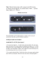
available. For optimal audio quality, you should adjust the input trim knob  
so that your loudest recorded signal lights up the yellow light, but not the  
red. When the red meter light shines extra bright – you’ve clipped! If the  
signal level ever exceeds 0dB FS the signal will be “clipped” and you  
will hear a “pop” or “tick” in the recording. This is a very bad thing, and 
clipping should be avoided at all costs! There is enough headroom so 
that you can be conservative in this area, and there is no need to push 
the input levels right up to the edge of clipping. 
 
3. Gain selector switch: if the switch is down, the voltage of signal will be 
   enlarged 10 times. It always used in the mic in situation. 
 
4. There is also an 1/4” stereo monitor headphone output jack, with a 
corresponding volume knob, and you also can select “analog output 
1/2” , “analog output 3/4”, “analog input 1/2”, and “analog input 3/4” with 
the button by side, the LEDs will show which it is. 

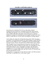
Audiolink Pro 24/96’s rear panel:

1. Power Supply Jack: DC 6-9V input. If Power Supply on the USB port is 
not enough, please use the an external Power Adapter for power supply. 
Especially when you use the phantom power(+48V). 
 
2. USB Jack, please connect it to the USB 2.0 port On PC with the USB 
cable. 
3. A phantom power switch (+48V) and an amber power indicator light. 
To enable phantom power, press the button l48V (the +48V 
LED will light up) and phantom power will be provided to the microphone 
inputs 1-2. Phantom power will not be applied to any line level equipment 
or guitars plugged in using cables with ¼” connectors. 
 
4. S/PDIF In & Out Interface: 
These S/PDIF connectors are used to transmit digital audio data between 
digital audio devices via an electrical signal. When connecting devices to 
the S/PDIF jacks, the use of standard analog RCA audio cables is not 
recommended. For reliable S/PDIF operation, 75-ohm coaxial cables are 
recommended. This port is no. 5-6 in the ASIO driver. 
 
5. MIDI In & Out Interface: 
The MIDI ports can be used for receiving MIDI time code (MTC), or  

12

Summary of Contents for Audiolink Pro 24/96

Page 1: ...r mit Input Gain Control Regler 2 x HI Z Gitarren Preamp Latenzfreies Hardware Monitoring am Kopfh rer Ausgang Regelbarer Stereo Headphone Output MIDI I O USB Powered USB 2 0 High Speed Hochwertiges A...

Page 2: ...dramatisch Wir w nschen Ihnen viel Spass bei diesem H rgenuss Im Verlauf dieser Bedienungsanleitung werden wir einige Hinweise zur Installation und Funktion des Audiolink Pro 24 96 geben Technische D...

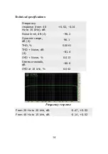
Page 3: ...dB 0 02 0 14 Noise level dB A 96 2 Dynamic range dB A 96 1 THD 0 0061 THD Noise dB A 81 4 IMD Noise 0 013 Stereo crosstalk dB 80 0 IMD at 10 kHz 0 042 Frequency response From 20 Hz to 20 kHz dB 0 47 0...

Page 4: ...4 daneben 2 weitere Klinken Buchsen als LINE Eing nge 3 und 4 die DIN Buchsen f r das MIDI I O sowie 2 Chinchbuchsen f r den S PDIF Digital Ein und Ausgang Ebenso ein Schalter f r die Phantomspeisung...

Page 5: ...miditech de finden Sie unter Downloads neben dieser Bedienungsanleitung auch einen Windows MME ASIO 2 Treiber f r das Audiolink Pro 24 96 der f r den Betrieb des Audiointerfaces erforderlich ist Bitt...

Page 6: ...seite bet tigen Nur am XLR Eingang Ein Instrument E Gitarre oder E Bass wird in der Mitte der Combo Buchse eingesteckt Mit dem Gain Reglern neben den XLR Klinken Eing ngen regeln Sie den Eingangspegel...

Page 7: ...ngsfrei LINE Eing nge 3 und 4 6 3mm Klinke R ckseite An diesen zus tzlichen Stereo Eingang k nnen Sie ein LINE Ger t wie einen CD Spieler MP3 Player oder ein Keyboard mit seinem analogen Output anschl...

Page 8: ...phantom power and input gain control 2 x HI Z guitar preamps Low latency hardware monitoring for LINE In 1 4 and LINE Out 1 4 Adjustable Stereo headphone output MIDI I O USB powered USB 2 0 high spee...

Page 9: ...s musical instruments etc Installation Complete installation consists of logging in as an administrator installing the Windows drivers into your system connecting the audio interface to a USB port and...

Page 10: ...d gets it s full high speed functionality you must use an USB 2 0 port The Interface is compatible to USB 3 but it do not use this bandwith Please plug your Audiolink Pro 24 96 to the USB port in the...

Page 11: ...k Pro 24 96 s front panel 1 Two universal inputs 1 2 with meters and trim knobs The universal input connections can accept balanced or unbalanced signals via or XLR connectors Since your Audiolink Pro...

Page 12: ...e the LEDs will show which it is Audiolink Pro 24 96 s rear panel 1 Power Supply Jack DC 6 9V input If Power Supply on the USB port is not enough please use the an external Power Adapter for power sup...

Page 13: ...omer Service If you experience any trouble with your Miditech hardware please go to the supportarea of our website at www miditech de and check out the FAQ s we have there If you can t find a solution...

Page 14: ...z to 15 kHz dB 0 02 0 14 Noise level dB A 96 2 Dynamic range dB A 96 1 THD 0 0061 THD Noise dB A 81 4 IMD Noise 0 013 Stereo crosstalk dB 80 0 IMD at 10 kHz 0 042 Frequency response From 20 Hz to 20 k...

Page 15: ...Grounding Precautions should be taken so that the grounding capabilities of the unit are not undermined The Audiolink Pro 24 96 provided with a cord with an equipment grounding conductor and groundin...

Reviews: