background image


A-1477/A-14167, Rev. 0 

Page 23 of 37 

Manual content is subject to change.  

Visit midlandmfg.com for latest manual revision and revision history. 


Spring Inspection 

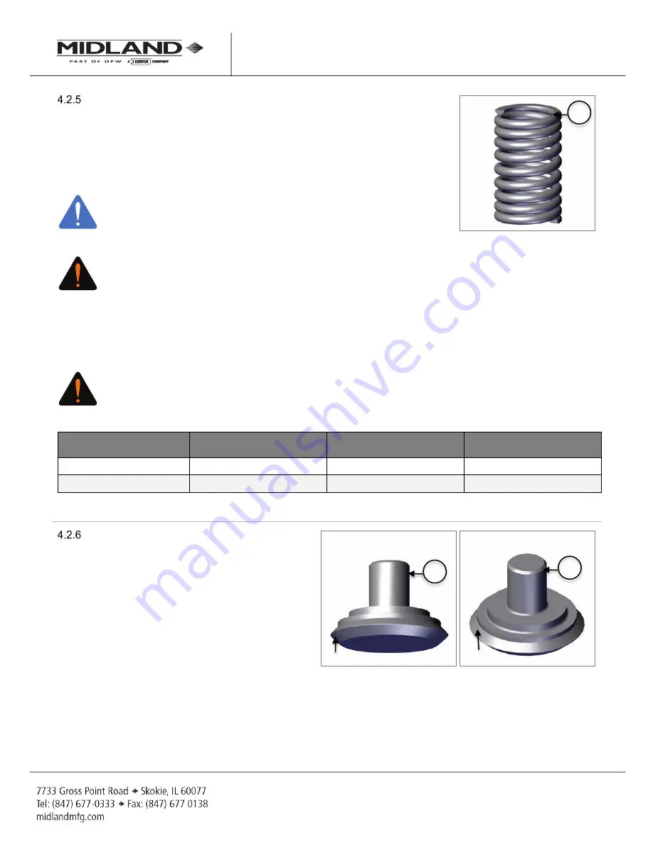
The  spring  (item  5)  is  a  highly  stressed  part.  The  exterior  surface  must  be 
free  of  pitting,  cracks  and  corrosion.  If  necessary,  use  magnetic-particle  or 
dye-penetration  inspection  (performed  by  certified  and  trained  personnel)  to 
evaluate the exterior surface and ensure that it is free of cracks and corrosion 
pits. If any excessive wear over 0.030” of the area is measured or observed, 
the spring cannot be repaired and must be replaced. 


NOTE:

 Use of Enhanced Inspection Methods, 

(LPI, MPI, etc.) is recommended.  


Figure 4-22 Spring Inspection 


WARNING: Valve-Spring Failure.

 Defects in coil springs, such as cracks and corrosion pits, can act as 

stress concentrators. Failure to detect these defects can result in coil-spring breakage and uncontrolled 
valve venting. 

Test the springs by pressing them to 80% of maximum deflection in a press for two (2) minutes. Remove from 
the press and then measure the spring free-height. If free-height is less than the minimum indicated in Table 4-
2, replace the spring. 


WARNING: Deficient Valve Travel.

 Coil springs that have taken a “set,” resulting in an undersized free-

height, will not allow the valve to open fully. The spring should not be bowed more than 1/4" when in the 
assembled position. Bowing in excess of this amount can cause the spring to rub against the inside wall 
of the nozzle or guide tube and adversely affect the pressure settings. If any of the defects mentioned 
above are observed, the spring cannot be repaired and must be replaced. 

Spring Part Number 

Wire Size (REF) (Inches) 

Height at 80% of Max. 

Deflection (Inches) 

Minimum Free-Height 

(Inches) 

15-150-MO 

0.28 

2.8 

4.00 

15-225-SS 

0.28 

3.13 

4.80 

Table 4-2 Minimum Free-Heights for Spring After Pressing 80% of the Maximum Deflection for Two (2) Minutes 


Plug Inspection 

Visually inspect the plug (item 3) paying close 
attention to sealing surfaces. It should be free 
of corrosion, nicks, dents, scratches and pits.   

Since  the  O-rings  must  seal  against  these 
surfaces,  any  irregularities  can  cause  the 
valve  to  leak.  Clean  these  areas  by  sanding 
lightly with emery paper (400-grit). If this does 
the effectively clean the part, replace this part.  
The  plug  must  be  free  of  gouge  marks, 
corrosion, pits and rust. If present, this part is 
rejectable and should be replaced. 

The  sealing  surface  is  the  crown  of  the  seat. 
Clean  the  seat  with  emery  paper  (400-grit) 
then  wipe  it  clean  with  a  cloth  and  a  suitable 
solvent. Run your fingernail aroudn the surface 
to detect any flaws. If any flaws are found, the 
part is rejectable and should be replaced.  


Figure 4-23 Plug Inspection 

NOTICE

WARNING

WARNING

 5 

 3 

 3 

Seat Sealing Surface 

O-Ring Sealing Surface 

Summary of Contents for A-14167 Series

Page 1: ...uary 20 2017 Supersedes N A External Style Pressure Relief Valve A 1477 A 14167 Series Installation Operation Maintenance IOM Manual Manual content is subject to change Visit www midlandmfg com for latest manual revision and revision history ...

Page 2: ...lations 3 Safety Warnings and Precautions 3 Introduction 5 Valve Details 5 Valve Installation 12 Installation Procedure and Required Tools 12 Leak Inspection 13 Valve Operation Notes and Precautions 13 I Valve Qualification 14 Valve Disassembly and Required Tools 14 Component Inspection 20 Valve Reassembly and Required Tools 27 Testing Process 32 Post Test Final Assembly 34 S Routine Maintenance 3...

Page 3: ...r to performing any work WARNING Toxic Hazard Always use extreme caution and proper equipment when involved with hazardous materials To avoid exposure to toxic or hazardous materials make sure the tank car is empty and clean and that the work area is free of hazardous chemicals before removing or installing any valve Wear protective clothing and equipment suitable for withstanding the materials to...

Page 4: ...rosion pits can act as stress concentrators Failure to detect these defects can result in coil spring breakage and uncontrolled valve venting CAUTION Deficient Valve Travel Coil springs that have taken a set resulting in an undersized free height will not allow the valve to open fully The spring should not be bowed more than 1 4 when in the assembled position Bowing in excess of this amount can ca...

Page 5: ... 23 1 NAMEPLATE STAINLESS STEEL SEE TABLE BELOW 24 1 BODY INSERT 3 SEE TABLE BELOW SEE TABLE BELOW 25 8 SOCKETED HEAD CAP SCREWS 316 STAINLESS 2 14 250 MOTF 26 1 RING 1 STAINLESS STEEL 14 260 SS 27 1 O RING 226 VITON A 15 27 VA 28 1 FLUE PLASTIC 5 14 24 PC 29 1 CAP CHAIN ASSEMBLY POLYETHYLENE SS 14 311 PE SS 30 1 FLUE O RING VITON A 14 27 VA NOTES 1 GREEN ETFE COATED PER DRG 14 142 2 BLACK PTFE CO...

Page 6: ...ABLE BELOW 24 1 BODY INSERT 3 SEE TABLE BELOW SEE TABLE BELOW 25 8 SOCKETED HEAD CAP SCREW 316 STAINLESS 2 14 250 MOTF 26 1 RING 1 STAINLESS STEEL 14 260 SS 27 1 O RING 226 VITON 14 27 VA 5 NOTES 1 GREEN ETFE COATED PER DRG 14 142 2 BLACK PTFE COATED 3 ALTERNATE MATERIAL IS AVAILABLE 5 ALTERNATE MATERIALS ARE AVAILABLE 6 USE 15 116 SS SCREW FOR A 14167 VALVE Table 2 3 Valve Components Base Series ...

Page 7: ...TF 15 1 SEAL SCREW 1 STAINLESS STEEL 15 15 CSTF 16 4 CAP SCREW 2 316 STAINLESS 15 160 MO 17 18 1 WIRE SEAL SS WIRE LEAD SEAL 22 72 PB 19 1 RETAINER HASTELLOY B 14 19 HB 20 1 SEAT O RING VITON 10 10 VG 5 21 1 PLUG O RING VITON 10 11 VG 5 22 23 1 NAMEPLATE STAINLESS STEEL SEE TABLE BELOW 24 1 BODY INSERT 3 KYNAR PVDF 14 240 KY 25 9 SOCKETED HEAD CAP SCREWS 316 STAINLESS 2 14 250 MOTF 26 1 RING 1 STA...

Page 8: ...of 37 Manual content is subject to change Visit midlandmfg com for latest manual revision and revision history Figure 2 1 Valve Component Identification Section B B Base and XX S01 Series NOTE Parts indicated in XX S01 Series only ...

Page 9: ...A 14167 Rev 0 Page 9 of 37 Manual content is subject to change Visit midlandmfg com for latest manual revision and revision history Figure 2 2 Valve Component Identification Section A A Base and XX S01 Series ...

Page 10: ... 1477 A 14167 Rev 0 Page 10 of 37 Manual content is subject to change Visit midlandmfg com for latest manual revision and revision history Figure 2 3 Valve Component Identification Section B B 3KY Series ...

Page 11: ... 1477 A 14167 Rev 0 Page 11 of 37 Manual content is subject to change Visit midlandmfg com for latest manual revision and revision history Figure 2 4 Valve Component Identification Section A A 3KY Series ...

Page 12: ...alve and then insert a soft rubber plug into the tank opening to prevent debris from entering the tank during cleaning of the valve mounting groove and studs on the manway cover plate Using a wire brush brush the threads of the mounting studs to remove rust or scale Nuts should move freely on clean studs Studs should not exhibit excessive corrosion Inspect threads for any sign of excessive wear co...

Page 13: ...Manufacturing for torque requirements as max torque may vary by valve model Do not exceed 200 ft lb NOTICE This is for installation to the car so the pattern is on the outside bolts CAUTION Uneven Gasket Compression Do not over tighten the nuts on one side of the valve as this may tilt the valve and result in uneven gasket compression TIP Use a 1 1 4 wrench to tighten mounting nuts Figure 3 1 Tigh...

Page 14: ...Valve Disassembly and Required Tools SAE Wrenches Component s Description Item 7 16 Socket Wrench Seat Screws 15 1 1 2 Wrench Top Locknut 8 3 4 Wrench Adjustment Screw 11 9 16 Socket Wrench Cap Screws 16 3 16 Hex Head Allen Wrench Socket Head Cap Screws 25 Other Tools Supplies and Equipment Wire Cutter Seal Wire 18 Non Scratching Tool O Rings 20 21 27 Table 4 1 Required Tools for Valve Disassembly...

Page 15: ...16 connecting the top guide item 1 to the body item 4 TIP Use a 9 16 socket wrench to remove the cap screws item 16 Figure 4 3 Remove Cap Screws Ease assembly press up to safely release the spring pressure from the assembly CAUTION Spring loaded Assembly During valve spring disassembly the valve contains springs under load DO NOT attempt to disassemble the valve without first reading these instruc...

Page 16: ...xposing the valve spring internal components for disassembly Figure 4 4 Remove Cap and Top Guide Remove follower 6 spring 5 and guide 7 Figure 4 5 Remove Follower Spring and Guide Remove stem item 2 Figure 4 6 Remove Stem Remove seal retainer item 12 and shaft seal assembly item 10 and remove seal from the retainer Figure 4 7 Remove Retainer and Shaft Seal Assembly 1 14 5 7 6 2 12 10 ...

Page 17: ...emove plug item 3 with O ring item 21 Remove O ring item 21 NOTICE To ensure best practices and consistency of the qualification process O rings should always be replaced TIP Use a non scratching tool to remove O ring item 21 Figure 4 9 Remove Plug and O Ring Disassemble the cap item 14 and top guide item 1 assembly by cutting the seal wire item 18 and remove the seal screw item15 TIP Use a 7 16 s...

Page 18: ...the top locknut item 8 TIP Use a 1 1 2 wrench to remove the top locknut item 8 Figure 4 13 Remove Top Locknut Remove the adjusting screw item 11 with loosened top locknut item 8 from the top guide item 1 Separate the top locknut from the adjusting screw TIP Use a 3 4 wrench and a 1 1 2 wrench to remove the adjusting screw item 11 Figure 4 14 Remove Adjusting Screw and Top Locknut Disassemble the b...

Page 19: ...ss steel ring item 26 Remove the body insert item 24 Figure 4 16 Remove Ring and Body Insert Remove the O ring item 27 from the body insert item 24 NOTICE To ensure best practices and consistency of the qualification process O rings should always be replaced TIP Use a non scratching tool to remove O ring item 27 Figure 4 17 Remove O Ring NOTICE 24 26 4 27 24 ...

Page 20: ...e Testing standards and practices The best inspection methods can miss defects when applied incorrectly A program developed under the guidance of a qualified American Society of Non Destructive Testing ASNT Level III Technician is recommended to achieve desired results Within such a program specific evaluation criteria for cracks pitting etc that would identify a part as defective will need to be ...

Page 21: ...ical tolerances cannot be provided the disposition of the internal integrity and surface quality of parts is under the jurisdiction of the repair facility and dependent on its experience and judgment NOTICE Without consent from the valve manufacturer or car owner repair work is limited to cleaning and polishing See AAR M1002 Paragraph A3 11 1 of the Tank Car Specifications Adjusting Screw Threads ...

Page 22: ...anufacturer or car owner machining grinding welding or other alterations to the valve seat or stem seat is not allowed per AAR M1002 Paragraph A3 11 1 of the Tank Car Specifications Stem Concentricity The valve stem must be straight within 0 025 maximum If the measurements are greater than 0 025 replace the stem NOTICE Valve stem concentricity can be checked using a uni level concentricity fixture...

Page 23: ...o open fully The spring should not be bowed more than 1 4 when in the assembled position Bowing in excess of this amount can cause the spring to rub against the inside wall of the nozzle or guide tube and adversely affect the pressure settings If any of the defects mentioned above are observed the spring cannot be repaired and must be replaced Spring Part Number Wire Size REF Inches Height at 80 o...

Page 24: ...ng surfaces and seat It should be free of nicks dents scratches and pits On the underside of the valve body item 4 is the surface that the valve to the mounting plate on the railcar Visually inspect for gouges or corrosion Use a flashlight and or magnifying glass if you are uncertain about the condition of this sealing surface If flaws are unreparable replace this part Figure 4 25 Body Insert Insp...

Page 25: ...ent this part is rejectable and should be replaced Figure 4 27 Valve Body Inspection Steel Ring Visually inspect the steel ring item 26 Clean and inspect the surface by sanding with emery papter 400 grit If this does not effectively clean the surface replace this part Figure 4 28 Steel Ring Inspection Seal Retainer Visually inspect the seal retainer item 12 Clean and inspect the surface by sanding...

Page 26: ...th Midland for recommended repair techniques when applicable Figure 4 30 Elastomer Inspection Special Inspection Considerations Previous procedures may not cover all conditions encountered in the field Therefore it is the responsibility of the repair agency to obtain approval from Midland for inspection evaluation repair and maintenance procedures not covered herein Facilities performing recommend...

Page 27: ... 7 16 Socket Wrench Seat Screws 15 1 1 2 Wrench Top Locknut 8 3 4 Wrench Adjustment Screw 11 9 16 Socket Wrench Cap Screws 16 3 16 Hex Head Allen Wrench Socket Head Cap Screws 25 Other Tools Supplies and Equipment Wire Cutter Seal Wire 18 Non Scratching Tool O Rings 20 21 27 Pipe Wrench Thread Lubricant Table 4 3 Required Tools for Valve Reassembly Figure 4 31 Valve Exploded View 1 11 14 29 28 5 2...

Page 28: ...s item 25 TIP Use a 3 4 Allen Wrench to install cap screws item 25 Torque to 75 in lb Figure 4 32 Install O Ring Body Insert and Steel Ring into Body Mount the plug O ring item 21 into the plug item 3 Figure 4 33 Mount Plug O Ring Place plug assembly item 3 into the body item 4 Figure 4 34 Place Plug Assembly into Body Insert the retainer O ring item 20 into the retainer item 19 Figure 4 35 Insert...

Page 29: ...igure 4 36 Insert Plug Assembly Insert the shaft seal item 10 into the seal retainer item 12 Figure 4 37 Insert Shaft Seal Place the seal retainer item 12 assembly onto the body item 4 Figure 4 38 Insert Seal Retainer Insert the stem item 2 into the body item 4 assembly NOTICE Check that the spring guide move smoothly inside the top guide Figure 4 39 Insert Stem into Body NOTICE 2 4 10 12 19 4 3 4...

Page 30: ...m item 2 Figure 4 40 Place Spring Guide Place the spring item 5 onto the spring guide item 7 Figure 4 41 Place Spring Insert the follower item 6 onto the spring item 5 Figure 4 42 Insert Follower Lubricate the threads of the top guide item 1 and adjusting screw item 11 Screw the adjusting screw item 11 by hand TIP Use a 3 4 wrench Figure 4 43 Insert Adjusting Screw 7 2 7 5 5 6 11 3 ...

Page 31: ...ealing surface is free of damage or debris The threads of the adjuisting screw should be cleaned and lightly lubricated TIP Use a 1 1 2 wrench Figure 4 44 Install Top Locknut Place the top guide item 1 onto the assembly Figure 4 45 Place Top Guide Using a press compress and align the bolt holes of the valve Fasten four x4 bolts item 16 Tighten the bolts evenly by hand TIP Use a 9 16 socket Remove ...

Page 32: ...irst bubble leak Vapor tight is defined as the pressure at whch no bubbles are detected Midland recommends that no bubbles be observed for two 2 minutes at vapor tight Test Stand and Gauge Requirements It is recommended that the test stand mounting must be equivalent to the AAR M1002 figures E19 14 through E19 23 for the valve being tested The pressure gauge must meet the requirements of D4 5 Test...

Page 33: ...rt To Discharge STD and Vapor Tight Pressure VTP Settings 4 4 3 3 Reduce the air pressure until leakage stops and then reduce pressure to less than one half of the STD pressure Then slowly increase the pressure 4 4 3 4 Observe the STD pressure and then bleed off the pressure slowly to observe the VTP 4 4 3 5 Repeat this procedure to ensure performance The STD and VTP should be consistent NOTICE AA...

Page 34: ...ipe or blow away any remaining soap suds and water used in the testing Tighten top locknut item 8 while holding the position of the adjusting screw item 11 in place TIP Use a 1 1 2 wrench to tighten top locknut item 8 while holding the screw on flats with a 3 4 wrench Figure 4 47 Tighten Locknut While Holding Adjustment Nut in Place Mount the top gasket item 9 around the top of the top guide item ...

Page 35: ...eal wire item 18 through the set screw and wiring point on the top guide item1 Clamp and trim the seal wire item 18 Figure 4 51 Install Seal Wire Attach flue item 28 to the valve body item 4 Figure 4 52 Attach Flue Attach wire sieal rivit it to the cap item 29 and place cap on flue item 28 to complete the assembly Figure 4 53 Install Cap Permanently attach a metal tag to the valve body with repair...

Page 36: ...pair Defined Leak repair is the temporary remediation to a valve observed to be emitting product in an unintended manner Since leak repair is a temporary measure once the car is unloaded and pressure is relieved the valve should be removed for complete inspection repairs and full requalification in accordance to the car owners standard qualification and maintenance program Leak repair is unschedul...

Page 37: ... Copyright 2016 OPW Printed in USA 2016 Delaware Capital Formation Inc All Rights Reserved ...

Reviews: