A-1477/A-14167, Rev. 0
Page 31 of 37
Manual content is subject to change.
Visit midlandmfg.com for latest manual revision and revision history.
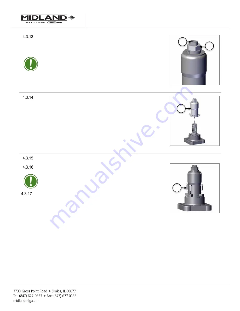
Screw the top locknut (item 8) onto the adjusting screw (item 11) by hand.
Inspect the body to verify that the sealing surface is free of damage or debris.
The threads of the adjuisting screw should be cleaned and lightly lubricated.
TIP:
Use a 1-1/2” wrench.
Figure 4-44 Install Top Locknut
Place the top guide (item 1) onto the assembly.
Figure 4-45 Place Top Guide
Using a press, compress and align the bolt holes of the valve.
Fasten four (x4) bolts (item 16). Tighten the bolts evenly by hand.
TIP:
Use a 9/16” socket.
Remove from the press.
Figure 4-46 Fasten Bolts
1
16
11
8


