10 |
P a g e 1 0 - 3 3 1 - 2 R E V A
MNChinook 200M Instructions
Check the blade rotation-
Once the blades have been fitted and secured to the chassis, ensure that they
rotate freely. Also take this opportunity to check that all of the blade and hub mounting screws are secure.
Remember that the blades are SHARP!
Fit the nose cone-
The nose cone can now be fitted to the rotor. This is done by aligning the 3 mounting
holes of the nose cone with those on the rotor hub plate. Use the 3ea M5 x 14mm hex head screws and 3
flat washers to secure the nose cone in position. Ensure that the nose cone runs concentrically (true) by
slowly spinning the rotor by hand. Loosening the screws and adjusting the nose cone position should
correct any misalign
ment or ‘wobble’. Make sure you do not over tighten the screws and crack the nose
cone (spinner).
Prepare the Turbine Mount-
To prepare your tower / mount bracket, you will need to drill a 6.5mm di-
ameter hole into the mast to secure the turbine. This hole should be drilled 18mm from the top of the tower
/ mount bracket and should be perpendicular to the surface. The hole should penetrate both sides and cross
the center line of the tubular section (go straight through).
Install the Transmission Wire-
When your tower or mount bracket is ready to have the turbine mounted,
the next stage is to run the wire from the top of the mount to where the electrical controller and batteries will
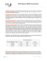
be located. Follow the table below to select the correct wire size. This will vary depending on your nominal
battery voltage and the distance that the cables will be run. Careful selection of the wire size is required. It
will not only affect the safety of the system, but also the overall efficiency. A wire of insufficient size will
cause a voltage drop, wasting the power that has been generated. The wire sizes listed below have been
selected with efficiency and cost in mind, as it is unlikely that your turbine will be running at full capacity
100% of the time. If in doubt, consult your local electrical supplier. The wire should be installed in
accordance with local electrical regulations and guidelines. If in doubt, use a local electrical contractor to
complete the wire installation. See "Cable Strain Relief" on
page 12
.
Warning: If a wire of insufficient size is used, heat will build up in the wire causing a potential fire
hazard. Wire capacities quoted below are based upon AWG wire sizes.
Transmission Distance
Chinook 200M Output Voltage
30 Feet
90 Feet
300 Feet
12 Volts
8 AWG
6 AWG
Not Recommended
24 Volts
12 AWG
8 AWG
4 AWG
48 Volts
14 AWG
12 AWG
10 AWG
Mount the Chinook 200M Turbine on to the Support Structure-
Ensure that the previously installed
power transmission wires are not yet connected to any batteries
and are ‘shorted’ together. This will prevent
the turbine from operating during the installation process. Once this has been done, connect the turbine
output wires to the transmission wires using a terminal block with a minimum rating of 30 Amps. Move the

