background image


MNBE-B, D, D3R, E Instructions 

(continued) 


Rev: A  Page 9  of  10 

Battery Configuration:


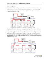
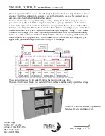
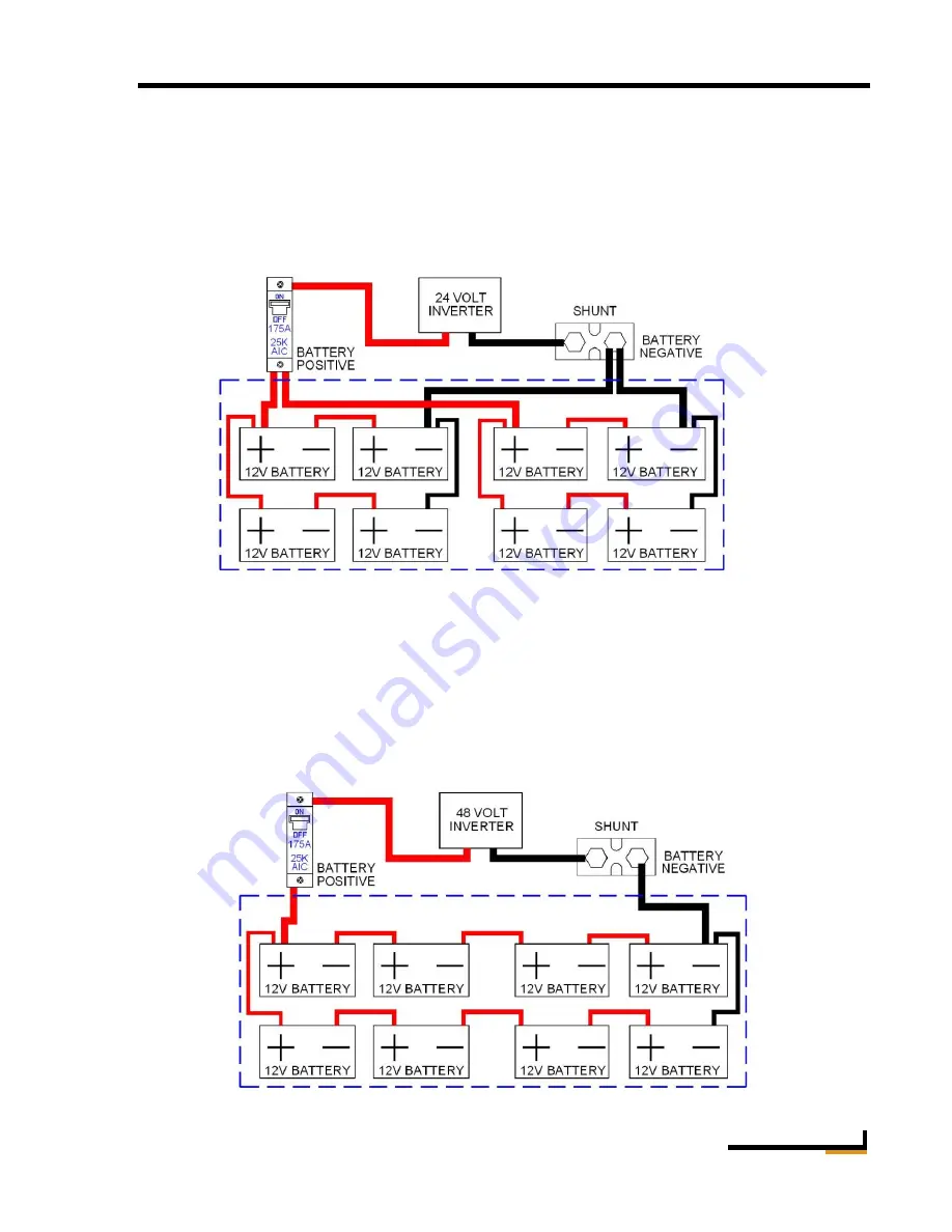
The MNBE-B is designed for eight batteries. The following diagrams show three different ways 

to configure the battery bank. This is not meant to show all methods of inter-connecting the 

battery bank.   It is the installer’s responsibility to ensure that all wiring conforms to NEC 

ANSI/NFPA 70 and all local codes. 


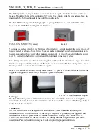
This configuration shows a 24 volt hook up using 12 volt group 31 batteries. Notice that in this 

configuration there are 4 parallel strings. Parallel strings can be a problem when too many are 

involved in cyclic applications such as in an off-grid installation. This set up poses no problems 

in a power back up application where batteries are normally floated. In an off-grid home, this 

battery bank would not be large enough for acceptable performance. You could add a couple 

more battery enclosures side by side, but the quantity of paralleled strings using these 12 volt 

batteries would be excessive. It would be advisable to go to 6 volt golf cart sized batteries to cut 

the paralleled strings in half.  


Summary of Contents for MNBE-B

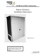
Page 1: ...R E Instructions Rev A Page 1 of 10 Battery Enclosure Installation Instructions These instructions are for the assembly of Midnite Solar Battery Enclosure models MNBE B MNBE D MNBE D3R and MNBE E MNBE...

Page 2: ...ombiner cover the modules with an opaque material before servicing any connected equipment Never attempt to charge a frozen battery When it is necessary to remove a battery make sure that the battery...

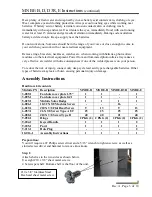
Page 3: ...re consequences if one of the welded pieces is on your person To reduce the risk of injury connect only deep cycle lead acid type rechargeable batteries Other types of batteries may leak or burst caus...

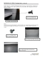
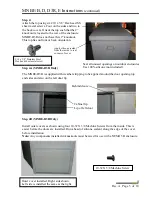
Page 4: ...ts see step 4B Step 3 Install the back panels Both panels are identical Make sure to orient them so that the knock outs are located in the upper half of the panel You will use 10 x 3 8 Hex head SS she...

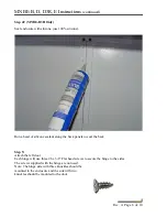
Page 5: ...t door lip Step 4B MNBE D3R Only Install outer covers as shown using four 10 32 X 3 8 Machine Screws from the inside This is easier before the doors are installed Run a bead of silicone sealant along...

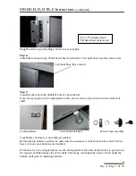
Page 6: ...ne sealant along the back panels to seal the back Step 5 Attach the left door Each hinge will use three 6 x 3 8 Flat head screws to secure the hinge to the sides The screws supplied with the hinge are...

Page 7: ...gn with slot in the bottom of shelf Lock Installed Lock shown latched Parts of lock assembly Your Battery enclosure is now fully assembled Before placing batteries on shelves make sure the enclosure i...

Page 8: ...onnected together side by side for additional storage 2 conduit knock outs are provided on each side of the enclosure to accommodate this configuration Use a 6 long conduit to connect the two cabinets...

Page 9: ...t group 31 batteries Notice that in this configuration there are 4 parallel strings Parallel strings can be a problem when too many are involved in cyclic applications such as in an off grid installat...

Page 10: ...hus good for 1260 watt hours Eight of these batteries yields 10 080 watt hours No matter how these batteries are configured they will still be the same watt hour battery bank Be careful when looking a...

Reviews: