background image

MND3RACCPLME (continued) 


6 | 

P a g e                                                                                                                       1 0 - 2 2 0 - 1         R E V :   B


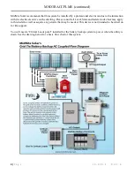
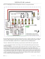
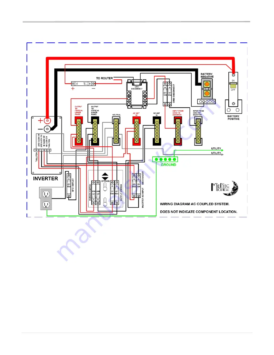
Here is a wiring diagram of the Pre Wired portion of the box as it ships from MidNite. 


Before starting this project please make sure the Grid tie inverter is off line and make sure you follow all 
necessary safety precautions. Always shut off all AC power before working on any circuits. Also make 
sure to switch off the Battery breaker in the AC coupled system before installing batteries.  
 
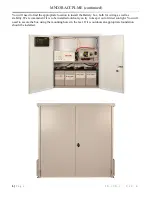
There are 3 distinct electrical connections you need to make to the Pre Wired AC coupled system: 
 
1-A 4 wire 120/240VAC branch circuit 30 amps or less from the utility Main panel to the buss bars 
Labeled “AC Hot In” 
2-A 4 wire 120/240VAC circuit from the buss bars labeled “AC Out to Critical Loads panel” to the sub 
panel with the critical loads in it. This should be the same ampacity as the feeder in Step 1 above. 
3-The 120/240vac circuit from the Grid tied inverter should be removed from the utility main panel and 
wired to the buss bars labeled “Input from Grid Tie inverter”. Keep in mind this circuit is protected by a 
15 amp 120/240VAC breaker in the AC coupled box. The Magnum inverter is limited in the capacity of 
grid tie it can handle. If the grid tie system is greater than 15 amps at 240VAC please contact customer 
service at MidNite Solar for help designing the system. 
 

Summary of Contents for MND3RACCPLME

Page 1: ...Magnum AC Coupled In a D3R battery box MND3RACCPLME 7 22 15...

Page 2: ...other sources of power to the inverter are in the off position Then remove the negative terminal from the battery first To reduce risk of battery explosion follow these instructions and those publish...

Page 3: ...eserved MidNite Solar Inc reserves the right to revise this document and to periodically make changes to the content hereof without obligation or organization of such revisions or changes unless requi...

Page 4: ...rvice on the dwelling Please consult all Local State and federal codes that may apply to this install as well as acquire any permits that may be needed This device is not intended to be relied on for...

Page 5: ...cation to install the Battery box both for wiring as well as stability We recommend if it is to be installed outdoors you try to keep it out of direct sunlight You will need to secure the box using th...

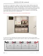
Page 6: ...branch circuit 30 amps or less from the utility Main panel to the buss bars Labeled AC Hot In 2 A 4 wire 120 240VAC circuit from the buss bars labeled AC Out to Critical Loads panel to the sub panel...

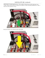
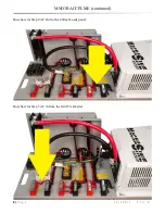
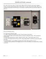
Page 7: ...Buss Bars for step 1 this is where the feeder from the utility main panel will connect The first picture shows the common AC Neutral as well as the Earth ground buss bar These 2 buss bars will be use...

Page 8: ...MND3RACCPLME continued 8 P a g e 1 0 2 2 0 1 R E V B Buss bars for Step 2 AC Out to the Critical Loads panel Buss bars for Step 3 AC in from the Grid Tie Inverter...

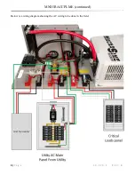
Page 9: ...MND3RACCPLME continued 9 P a g e 1 0 2 2 0 1 R E V B Below is a wiring diagram showing the AC wiring to be done in the field...

Page 10: ...d as you can see from the picture you simply need to slide the 4 batteries in and connect them in a series string for 24 vdc We are recommending the Concorde PVX3050T 6 volt batteries for this For oth...

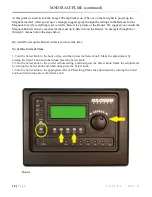
Page 11: ...neral use outlet 15 amp AC breaker for the general use outlet This should be on at all times Invert or Bypass Slider Up is Normal and down by passes the Magnum inverter This will normally always be up...

Page 12: ...ter To navigate through the 1 through 3 menus follow the steps below On initial Power up the Router will ask you to set the time To Set the Current Time 1 Turn the Select knob to the hour of day and t...

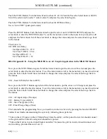
Page 13: ...knob to enter the Inverter menus To set the menu items scroll to the menu item you need to edit and press the Select knob Scroll the select knob to change the value and press the select knob to go bac...

Page 14: ...and keep an eye on the battery voltage The voltage should rise as the batteries are filled If the loads are too great on the critical load panel it may not rise if this is the case turn some loads of...

Page 15: ...pt for the warranty that the products are made in accordance with the specifications therefore supplied or agreed to by customer MIDNITE SOLAR MAKES NO WARRANTY EXPRESSED OR IMPLIED AND ANY IMPLIED WA...

Reviews: