SMA E-Panel installation manual
15 |
P a g e
1 0 - 2 3 4 - 1 R E V : A
System wiring
The SMA E-Panel is a complex system and should be wired by a qualified electrician.
Danger:
Hazardous voltages are present throughout the system. All power must be removed
before attempting any wiring or maintenance of the system.
Danger:
Il y a haute tension partout dans le système entière. Débrancher toutes les sources
d’alimentation avant faisant des connections ou l’entretien.
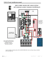
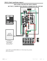
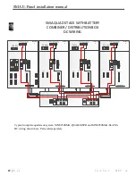
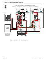
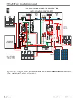
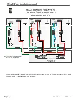
The following pages contain wiring diagrams for many configurations. Follow the appropriate one for
your installation such as on or off grid, AC Coupled or three phase. The diagrams below also cover
single, dual and quad systems with up to 7 Classic Charge Controllers. Components sold separately.
If you are unsure of any aspect of the installation contact a licensed electrician or MidNite Solar at
360.403.7207.
DC Wiring:
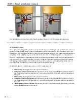
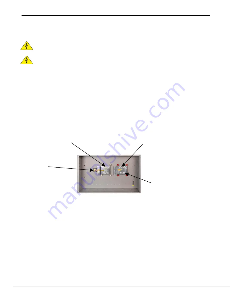
If using the optional Battery Combiner run 4/0 wire from the battery breaker to the positive connection
in the Battery Combiner and 4/0 wire from the E-Panel shunt. It is acceptable to use black wire if the
ends are clearly marked red or white as appropriate. Use copper wire of adequate gauge (Determined by
breaker size) rated for a minimum of 75°C. Always use approved conduit and fittings.
Use 4/0 wire for a 250 Amp battery breaker and 2/0 for a 175 Amp battery breaker.
Negative connections to inverters
Positive connections to inverters
Negative shunt connection
To batteries
For installations not using the Battery Combiner connect a positive wire from the E-Panel breaker to the
battery bank positive and a negative wire from the E-Panel shunt. These wires should be kept as short as
possible. Running the wires close together will reduce ripple currents.
AC Wiring:
This varies greatly depending on your system configuration. The following wiring diagrams show on and off
grid, with and without a generator, AC coupled and three phase systems. Please pay special attention to the
information on AC coupled systems. Use appropriate conduit and fittings for a safe, reliable, code compliant
system.
Slave units are shipped with red mounting blocks and covers for AC in and AC out installed. Black and blue
mounting blocks and covers are included. Should you desire to change the mounting blocks and covers to
match the desired wire color (L1 Black, L2 Red and L3 Blue) Simply pull the cover off, press the retaining
tab on the mounting block to release the terminal block and remove the terminal block. There is a Phillips
screw in each mounting block. Remove and retain the screw. Using the new color reverse the process to
reinstall. Note: Use caution when tightening the screws. The chassis can be stripped if the screws are over-
tightened. Should this occur the use a slightly longer #10 screw and a #10 nut from behind.
Positive connections to batteries


