SMA E-Panel installation manual
40 |
P a g e
1 0 - 2 3 4 - 1 R E V : A
MidNite Solar Battery Disconnect Module – MNBDM (Optional)
The Midnite Solar Battery Disconnect Module (MNBDM) is an optional circuit board which can be installed in most
MidNite Solar E-Panels. It is used in conjunction with one or more MNBH Disconnect switches and MidNite Solar
disconnecting combiners to remotely shutdown the system in emergencies. The MNBDM is controlled by the MNBH
Birdhouse Disconnect switch and disconnects the main batteries from the system in a similar manner as the
disconnecting combiner disconnects the PV array from the rest of the system. The trip signal for the MNBDMs and
combiners is generated by the MNBH Disconnect Panel. Control signals are provided to the target devices via a
ruggedized 600V CAT-5 cable, which connects all components in the system.
Power and Circuit Breaker Connections
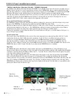
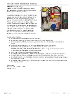
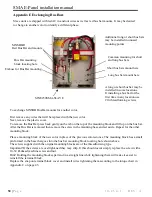
The MNBDM is powered from the main batteries and has terminals for connection to the E-Panel remote trip circuit
breaker, other MNBDMs, the disconnecting combiners and the MNBH Disconnect Panel.
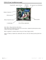
Electrical connections: First, Connect the battery negative to TB1 pin2 (-) then connect the switched battery positive
(after the battery breaker) to TB1 pin 1 (+). The MNBDM has onboard overcurrent protection but a circuit breaker
should be used to protect the wiring. The chassis ground connects to TB1 pin 3 (GND symbol).
Connect the red remote trip wire from the remote trip circuit breaker to TB2 pin 1 (+) and the black to TB2 pin 3 (-).
Leave TB2 pin 2 open (middle).
System Connections
There can be up to four MNBDMs in the system. All system components are connected together with CAT-5 cable
which plugs into the two RJ-45 (Ethernet-style) connectors, J1 and J2. There is no difference between the two
connectors. A typical BirdHouse installation consists of one MNBH Disconnect switch, one MNBDM and one
disconnecting combiner would use one of the RJ-45 jacks for connection to the MNBH switch and the other for
connection to the combiner. Connect one to the MNBH Disconnect switch, or to another MNBDM that connects to the
MNBH Disconnect switch. Connect the other to any downstream MNBDM units or combiners.
Operation
The MNBH Disconnect Panel must be energized and connected to an MNBDM before closing the battery circuit
breaker on the E-Panel. If you attempt to close the breaker without the MNBH on and the cable installed, the MNBDM
will detect a problem and trip the breaker within about 5 - 7 seconds. This is a fail-safe feature that requires the system
to be intact and working before energizing.
If the cable is properly installed the power will remain on and the system is now ready for operation. The MNBDM
LED will briefly blink (off) three times when power is first applied. This is normal and indicates that the board is
working properly. The system may be tested by pressing the button on the MNBH Disconnect Panel, but doing that will
trip every combiner and MNBDM in the system. To avoid this, a small test button is located on the front edge of the
MNBDM board. Pressing the test button only trips the one breaker in that panel. Note that there is 2 second delay after
pressing the button before the breaker trips.
TB1 Pin 1
Battery Positive
TB1 Pin 2
Battery Negative
TB1 Pin 3 Ground
TB2 Pin 1 Breaker
Trip Positive
TB2 Pin 3 Breaker
Trip Negative
No Connection

