background image


SMA E-Panel installation manual


8 | 

P a g e                                                                                                  

1 0 - 2 3 4 - 1         R E V :   A  


Mounting the SMA E-Panel to the wall: 


This section describes the general instructions for installing components to the wall or other mounting surface. When 
you have completed this section then refer to the appropriate section for your model for specific instructions on 
wiring and wiring diagrams.  
 
Pre-Wired systems start on Page 13. 
 

Note:

 The SMA E-Panel system should only be installed with the backplate. Failure to use the backplate can result in 

poor alignment of system components resulting in a less reliable and non-code compliant installation. 


Tools Required: 

Long #2 Phillips Screwdriver 
Medium slotted Screwdriver 
Torque Screwdriver for electrical connections 
9/16” Wrench 
Large Allen wrench for inverter DC connections 
Drill for pilot holes if required 


Be sure to comply with all local and national code requirements including National Electrical Code, ANSI/NFPA 70. 
Use Class 1 wiring methods for field wiring connections to terminals of a Class 2 circuit. Select the wire gauge used 
based on the protection provided by the circuit breakers/fuses. 


The SMA E-Panel is a type 1 enclosure suitable for installation in an indoor location protected from rain / snow etc. 


When installing the system make sure to observe NEC maximum height requirements. 


The system when complete will be quite heavy. Ensure that the wall can handle the weight of the system 
and use appropriate fasteners. Have help when positioning and mounting system components to the wall. 


Mise en garde! Cet appareil est assez lourd. S’assurer que le mur peut supporter le système. C’est nécessaire 
d’avoir assistance pour installer le système. 


High voltage is present throughout the system. Disconnect all sources of power and exercise extreme 
caution when working with, on or around this equipment. 


Attention: Il y a haute tension partout. Débrancher toutes les sources d’alimentation et faire attention autour 
de le système. Lire aussi le manuel de l’inverter pour plus des informations. 


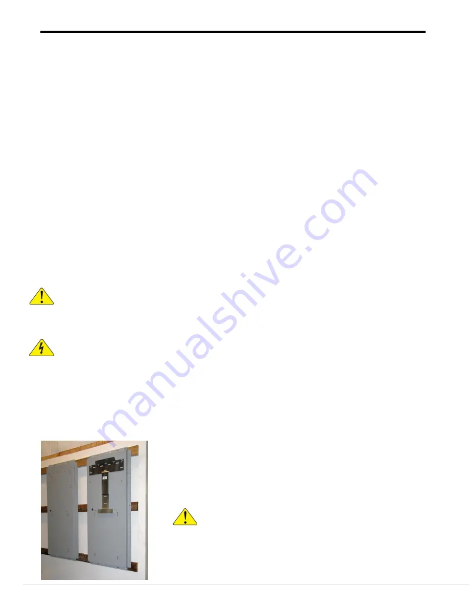
Install the backplate either MNESMA tall BP or MNESMA short BP to the selected surface using a minimum of four 
5/16 lag bolts with a minimum length of 2”. 
The inverter should be installed before the E-Panel. Use ¼-20 bolts to attach the inverter mounting bracket, E-Panel 
and MNX240 (if so equipped) to the backplate. The MNX240 requires the tall backplate. 


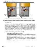
Left: MNSMA Short BP Backplate 
 
Typical backplate installation, shown mounted on wall with the inverter 
mounting bracket installed (inverter mounting bracket supplied with 
inverter). 
 

CAUTION:

 The inverter is 

extremely

 heavy. Use extreme 

caution when lifting the inverter. Refer to the inverter manual for 
safe and proper inverter installation instructions. Make sure the 
wall or other mounting surface can support the weight. 
 
Encore, cet appareil est 

tellement

 lourd, sauvegarder vous-même. 

Summary of Contents for MNE250SMA

Page 1: ...in the USA Canadian electrical codes have jurisdiction in Canada These instructions are not intended to be used in lieu of these local and federal codes but rather are used as specific to this produc...

Page 2: ...plate for AC coupled Master holds inv E Panel and autoformer MNESMA short BP Short back plate for inverter and E Panel MNX 240 6000 watt autoformer for single inverter AC coupled system Symbols used i...

Page 3: ...nstallation is recommended Wiring must be done in accordance with the National Electrical Code ANSI NFPA 70 Use Class 1 wiring methods for field wiring connections to terminals of a Class 2 circuit Us...

Page 4: ...e couver Pour toute r paration ou service d entretien consulter un agent sp cialis Il y a peut tre plusieurs sources d alimentation dans cette system D brancher toutes les interrupteurs avant toute d...

Page 5: ...23 24 47 Single 19 22 44 AC Coupled Dual 19 27 46 Off Grid Single 20 21 44 Off Grid Dual 25 26 Three Phase 28 29 Tightening torque for electrical connections 30 43 Classic Charge Controller with arc f...

Page 6: ...5 1 1 Grommets 1 9 314 1 2 Grommet 9 6 032 1 1 4 20 Bolts 4 to mount the e panel 5 extra to mount the inverter 2 6 010 2 2 M6 Screws and other hardware for mounting inverter to backplate 4 5 015 1 Ins...

Page 7: ...nput connections Ground Busbar AC Neutral busbar AC Input AC Output under charge controller breakers Charge Controller breakers DC Disconnect Breaker Relay trippable Bypass Breakers Dinrail for additi...

Page 8: ...tem when complete will be quite heavy Ensure that the wall can handle the weight of the system and use appropriate fasteners Have help when positioning and mounting system components to the wall Mise...

Page 9: ...ting on the mounting screws down on the screws and not slid up Mounting on back of inverter Inverter mounting bracket mounted to backplate Backplate mounted to wall The inverter rests on the tab of th...

Page 10: ...R E V A Mounting the SMA E Panel to the wall cont Inverter lower mounting screw locations The inverter is spaced away from the back plate at the four lower mounting screws These two mounting locations...

Page 11: ...up the E Panel mounting holes with the holes in the backplate Attach the E Panel to the backplate with 20 bolts Pressed in nuts are provided on the backplate Remove the deadfront metal front cover by...

Page 12: ...AC Coupled systems mounts above the inverter Position the MNX240 Autoformer above the inverter and line up the mounting holes Install with 20 hardware Plastic cover installation To install the cover...

Page 13: ...isassemble systems to mount them on the wall One way to install a pre Wired system is to find where the bottom of the backplate will be when installed and securely screw a 2x4 to the wall with the top...

Page 14: ...SMA E Panel installation manual 14 P a g e 1 0 2 3 4 1 R E V A Bottom knockout location Right Side knockout location Front Top...

Page 15: ...and 2 0 for a 175 Amp battery breaker Negative connections to inverters Positive connections to inverters Negative shunt connection To batteries For installations not using the Battery Combiner conne...

Page 16: ...ne inverter installed remove the top and bottom knockouts see image next page that face the other E Panel and push one of the fittings from the outside through the knockout opening into the E Panel In...

Page 17: ...t into one of the fittings installed in the previous step Remove the facing knockouts on the second inverter Move the second E Panel into place Secure the E Panel to the wall then secure the conduits...

Page 18: ...ter to the L2OUT busbar on the slave unit L2IN goes from the L2IN busbar on the master unit to the L2IN busbar on the Slave unit all in the lower conduit The ground can be in either conduit as is conv...

Page 19: ...cularly adept at this form of coupling giving you the best of both worlds of grid tie and power backup Generator hookup to a standalone system vs an AC coupled system Off Grid the generator goes to th...

Page 20: ...OFF ON OFF ON OFF ON OFF ON OFF ON OFF ON OFF ON OFF ON OFF ON OFF ON OFF ON OFF LOADS 120 V NORMAL BYPASS SPD 300 6V 400ah 6V 400ah 6V 400ah 6V 400ah 6V 400ah 6V 400ah 6V 400ah 6V 400ah 6V 400ah BATT...

Page 21: ...AC INPUT AC OUTPUT ON OFF ON OFF 60 60 ON OFF ON OFF 60 60 ON OFF ON OFF ON OFF ON OFF ON OFF ON OFF ON OFF ON OFF ON OFF ON OFF ON OFF ON OFF ON OFF ON OFF ON OFF LOADS 120VAC NORMAL BYPASS SPD 300 6...

Page 22: ...SMA E Panel installation manual 22 P a g e 1 0 2 3 4 1 R E V A Typical complete single system Parts sold separately...

Page 23: ...OUND BATTERY NEGATIVE BATTERY POSITIVE GROUND BATTERY NEGATIVE BATTERY POSITIVE GROUND L1 OUT L1 IN L2 OUT L2 IN NEUTRAL NEUTRAL NEUTRAL INVERTER 1 GROUND HOT OUT HOT IN 175 ON OFF ON OFF 60 A ON OFF...

Page 24: ...1 IN L2 OUT L2 IN NEUTRAL NEUTRAL NEUTRAL INVERTER 1 GROUND HOT OUT HOT IN 175 ON OFF ON OFF 60 A SPD 300 SPD 300 ON OFF 125 A ON OFF 125 A ON OFF 125 A ON OFF 125 A GROUND BATTERY NEGATIVE BATTERY PO...

Page 25: ...T IN 175 ON OFF ON OFF 60 A GROUND BATTERY NEGATIVE BATTERY POSITIVE GROUND ON OFF 60 A ON OFF 60 A AC INPUT AC INPUT AC OUTPUT AC OUTPUT ON OFF ON OFF 60 60 ON OFF ON OFF 60 60 ON OFF ON OFF ON OFF O...

Page 26: ...PUT ON OFF ON OFF 60 60 ON OFF ON OFF 60 60 ON OFF ON OFF ON OFF ON OFF ON OFF ON OFF ON OFF ON OFF ON OFF ON OFF ON OFF ON OFF ON OFF ON OFF ON OFF LOADS 120 240V NORMAL BYPASS SPD 300 SPD 300 6V 400...

Page 27: ...A SPD 300 SPD 300 BATTERY NEGATIVE BATTERY POSITIVE GROUND ON OFF 60 A ON OFF 60 A AC INPUT AC INPUT AC OUTPUT AC OUTPUT ON OFF ON OFF 60 60 ON OFF ON OFF 60 60 L2 OUT FROM INV 2 ON OFF ON OFF ON OFF...

Page 28: ...Y NEGATIVE BATTERY POSITIVE GROUND SMA 3 PHASE WITH BATTERY COMBINER DISTRIBUTION BOX NO BYPASS SWITCH DRAWN BY T CARPENTER 02 18 13 175 ON OFF 175 ON OFF 175 ON OFF ON OFF 60 A AC INPUT ON OFF 60 A A...

Page 29: ...3 PHASE WITH BATTERY COMBINER DISTRIBUTION BOX DC WIRING L3 L2 DRAWN BY T CARPENTER 02 05 13 L3 IN L3 OUT 60 60 175 ON OFF 175 ON OFF 175 ON OFF ON OFF 60 A AC INPUT ON OFF 60 A AC INPUT NEUTRAL L3 I...

Page 30: ...75 ON OFF 175 ON OFF ON OFF 60 A AC INPUT ON OFF 60 A AC INPUT NEUTRAL L3 IN L3 OUT COMM SYNCH IN COMM SYNCH OUT COMM SYNCH OUT COMM SYNCH OUT COMM SYNCH IN COMM SYNCH IN NOTE COMMUNICATIONS CABLES SH...

Page 31: ...ch pounds Installing and Wiring the Classic Charge Controller The MNCCP Dual Classic Mounting Plate Sold separately holds two Classics and is used with MidNite E Panels The MNCCP Dual ships with the M...

Page 32: ...Wind Hydro Conduit nipple Chassis ground Above Basic wiring connections to the Classic When selecting wire and breakers for the Classic or any device remember that the breakers are there to protect t...

Page 33: ...show charge controller wiring Each Classic requires an input and an output breaker Breakers are available from MidNite Solar in Dinrail style up to 63 Amps 150 Vdc and in panel mount up to 100 Amps 3...

Page 34: ...s is happening 1 There is an actual ground fault in the wiring or 2 there is an excess of current flowing through the large 63 or 80 amp breaker Be sure to check your wiring Refer to the wiring diagra...

Page 35: ...r and wire than the array output though The breaker is there to protect the wire not the controller so you can use a 63 amp breaker even if the controller is not capable of outputting more than 30 amp...

Page 36: ...winding configuration for the MNX 240 autotransformer One dual 60 Amp breaker provides the input output connection points for this unit The images on the following page depict the internal wiring conf...

Page 37: ...e it accessible and useful for the 120VAC Sunny Island In this configuration L1 and L2 240VAC power is applied to the 25Amp breakers of the MNX 240 Autotransformer 120VAC is then available from the ou...

Page 38: ...Tall Backplate Knockout Location The wiring from the E Panel to the Autoformer and back is routed behind the Tall Backplate A knockout is provided in the E Panel and in the AutoFormer with clearance h...

Page 39: ...Enclosure with locking door and one shelf Outdoor 3R rain type design Powder coated aluminum and stainless steel construction Holds four 8D batteries Comes with 250 amp battery breaker and has spaces...

Page 40: ...four MNBDMs in the system All system components are connected together with CAT 5 cable which plugs into the two RJ 45 Ethernet style connectors J1 and J2 There is no difference between the two conne...

Page 41: ...connecting and Arc Fault combiners Hard wired connection gives positive feedback that the Disconnect on the roof has actually been thrown Connection is via 600 1000v Cat 5 USE 2 cable Up to four separ...

Page 42: ...circuits installed on or in buildings shall include a rapid shutdown function that controls specific conductors in accordance with 690 12 A through D A Requirements for controlled conductors apply on...

Page 43: ...8 90 1 87 83 90 100 4AWG 44 38 63A 150V Classic 150 48 100 2 08 80 80 90 4AWG 38 46 50A 8AWG 63A 6AWG 150V Classic 150 48 110 2 29 76 80 90 4AWG 33 18 50A 8AWG 63A 6AWG 150V Classic 150 48 120 2 5 76...

Page 44: ...nnyBoy inverters can switch between off grid and grid tie mode automatically when RS485 boards are used To program this feature you must use either a SMA service cable USBPBS or SMA web box SUNNYWEBBO...

Page 45: ...hly recommended MNSPD 300 One surge protection device works for AC input and AC output MNX 240 240 to 120VAC Autoformer required to interface the 240V SunnyBoy to the 120V Sunny Island Classic Charge...

Page 46: ...nstallations To add Classic charge controller wiring add the bold text to end of part number CL150 1X CL150 2X CL200 250 1X CL200 250 2X Includes all wiring input and output breakers mounting plates a...

Page 47: ...ing protection and AC conduit connections Recommended options MNESMA Short BP Back Plate Highly recommended MN Battery Combiner 1000A Combiner for battery connections for 4 inverters Highly recommende...

Page 48: ...e SunnyBoy inverters can switch between off grid and grid tie mode automatically when RS485 boards are used To program this feature you must use either SMA service cable USBPBS or SMA web box SUNNYWEB...

Page 49: ...l terminal busbars Knockouts located for battery cables lightning protection and AC conduit connections Recommended options MNESMA Short BP Back Plate Highly recommended MN Battery Combiner 1000A Comb...

Page 50: ...lor in place of the previous colored ones The mounting block has a small pin formed in the base that goes into the bus bar mounting block locating hole shown above The screws supplied with the origina...

Page 51: ...ocks to remove mounting blocks Set screws aside New mounting block Note the mounting block locating pin Position new mounting blocks as shown Secure them with screws removed earlier Replace the Busbar...

Page 52: ...C Arlington WA 98223 425 374 9060 Purchasers must prepay all delivery costs or shipping charges to return any defective MidNite Solar product under this warranty policy Except for the warranty that t...

Reviews: