background image

Summary of Contents for NBA HANGTIME 40259

Page 1: ......

Page 2: ......

Page 3: ...THIS DECLARATION RELATES IS IN CONFORMITY WITH THE FOLLOWIN6 EUROPEAN PRODUCT SAFETI DIR cmf S ELECTROMAGNETIC COMPATABILITY DIRECTIVE 89 336 EEC AND AMENDMENTS 91 C162 08 92 31 EEC 93 68 EEC AS IS 1 RIFl D BYCOMPLIANCE WITH THE FOLLOWIN6 STANDARDS EN5014 1993 IEC 801 3 1984 EN61000 4 3 EN61000 4 5 1995 Date issued MARCH 15 1996 MANUFACTURE S SIGNATURE DON HASSLER V P MANUFACTURING EN61000 4 2 199...

Page 4: ......

Page 5: ...me serial number For your records white the game serial number in the manual PIC Number___________ Serial Number____________ Midway Manufacturing Company reserves the rights to make modifications and improvements to its products The specifications and parts identified in this manual are subject to change without notice ...

Page 6: ......

Page 7: ...Player Controls J 1 10 Control Panel Diagram 1 10 Game Operation 1 11 Control Switches 1 11 Control Switch Location Diagram 1 11 Menu System Operation 1 12 Operation 1 12 Main Menu 1 12 Diagnostic Tests 1 13 Switch Test 1 13 DIP Switch Test Table 1 14 Video Section Test 1 15 0 Sound Section Test 1 15 Monitor Patterns 1 16 Run Burn in Test 1 16 Coin Bookkeeping 1 17 Game Audits 1 17 Game Adjustment...

Page 8: ...ol Panel 2 2 Fluorescent Lamp Assembly 2 3 Speakers 2 3 Fuses 2 3 Cables 2 3 Monitor 2 3 Manuals 2 3 Line Cord Application Chart 2 4 Coin Door Chart 2 4 Rear Door Assembly 2 5 Switching Power Supply Assembly 2 6 CPU Board 2 7 Section 3 Cabinet Wiring 3 1 JAMMA Chart 3 2 Power Wiring Diagram 3 3 Main Wiring Diagram 3 4 Notes 3 4 Copyright 1996 MIDWAY Manufacturing Company 11 ...

Page 9: ...NBA HANGTIME Operation 1 1 SECTION ONE ...

Page 10: ...se in fuse type voltage rating and current rating HANDLE FLUORESCENT TUBE AND CRT WITH CARE If you drop a fluorescent tube or CRT and it breaks it will implode Shattered glass can fly eight feet or more from the implosion ATTENTION PROPERLY ATTACH ALL CONNECTORS Make sure that the connectors on each printed circuit board PCB are properly connected If the connectors do not slip on easily do not for...

Page 11: ...tall one leg leveler with its hex nut in each hole 4 Stand the cabinet upright and make certain that it is in a stable position Level the cabinet 5 Remove the rear door of the cabinet Inspect the interior for any signs of damage Check all major assemblies to assure that they are mounted securely 6 Refer to the games Cabinet Wiring Diagram section 3 to assure that all cable connectors are correctly...

Page 12: ...connectors into the appropriate cabinet cable connectors Be sure to match up the wire colors when you plug the connectors into each other See the Cabinet Wiring Diagram in Section 3 of the game manual DO NOT FORCE THE CABLE CONNECTORS Attach the ground strap from the cabinet under wing nut Lower the control panel and reach through the coin door to close the latches on the left and right sides of t...

Page 13: ...ck the cables turn Off and unplug the game Reach through the coin door undo the latches and tilt the control panel forward until it rests on its support brackets Recheck the cable connections 14 Once you are sure the connections are correct close and latch the control panel Close and lock the coin door Plug the game in and turn it On All buttons and joysticks should function normally NOTICE Velcro...

Page 14: ...Fluorescent Lamp Assembly Speaker Assembly Control Panel Assembly Coin Door Blank 25 Monitor Bezel Cabinet Assembly Front 1 6 ...

Page 15: ...Cabinet Assembly Rear On Off Switch Vent Cover Rear Door Assembly 1 7 ...

Page 16: ...1 2 thoroughly before beginning this procedure Switch OFF power to the game Remove the viewing glass and the monitor bezel Completely disconnect the monitor from all of its cabling Remove the four flange nuts securing the monitors mounting flanges to its mounting panel Pull the monitor carefully from the cabinet front CAUTION The monitor DOES NOT require isolation from A G line However when servic...

Page 17: ...tches are located on a small bracket on the coin door The Begin Test Switch on the right activates the game s menu system The Service Credit Switch on the left allows credits to be allotted for service testing without affecting the game s bookkeeping total Coin Door Button Locations I I I SERVICE VOLUME BEGIN I CREDITS DOWN UP TEST I 0 0000 i ESCAPE ENTER I I I 1 9 TILT SWITCH ...

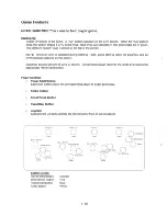
Page 18: ...lect which player receives the credit by pressing the appropriate Player Start Button Player Controls Player Start Button Each start button allows the corresponding player to begin game play Turbo Button Shoot Block Button Pass Steal Button Joystick Each players Joystick controls the movement of their on screen player PLAYER 1 0 START BLUE JOYSTICK 0 SHOOT BLOCK Oo 0 PASS STEAL TURBO Button Colors...

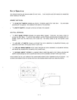
Page 19: ...Switch or use the Service Credit Switch The VOLUME UP SWITCH moves up through the menu selections or adjustment choices and raises the sound level of the game when in game play The VOLUME DOWN SWITCH moves down through the menu selections or adjustment choices and lowers the sound level of the game when in game play The SERVICE CREDIT SWITCH is a special feature switch that allots credit without a...

Page 20: ...ay act upon as desired Press the Test Mode Switch to activate the Main Menu shown below Game adjustments bookkeeping and diagnostics are all accessible from this menu Use any joystick to select desired menu option press any control panel button to activate it Notice that the options are highlighted in sequence Note Only highlighted options can be activated Main Test Menu 1 12 ...

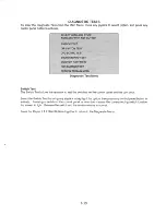
Page 21: ...o test the switches on the control panel and the coin door Select the Switch Test by using any joystick to highlight the option then press any control panel button to activate Pressing a switch on the control panel or coin door causes the corresponding switch location the screen to light Release the switch and the screen returns to normal Press the Player 1 2 Start Buttons together to return to th...

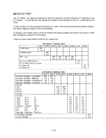
Page 22: ...ch Test DIP S h 1 S T bl w1tc ett1ng a e SW1 SW2 SW3 SW4 SW5 SW6 SW7 swa Test Switch Off On Powerup Test Off On Not Used Off Off Off Off On On On On No Dollar Bill Validator Off Dollar Bill Validator Installed On 4 Player Kit Off 2 Player Kit On DIP S h 2 S T bl w1tc ett1ng a e SW1 SW2 SW3 SW4 SW5 SW6 SW7 swa One Coin Counter 1Count Coin Off Off One Coin Counter Totalizing On Off Two Coin Counters...

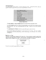
Page 23: ... show the layout of the RAMs and ROMs on the CPU Any chip that is shown as gray with a white outline and should turn green during the CPU Test During the test chips are good if they turn green they are faulty if they turn red Press and hold start button to exit the CPU Board Test Sound Section Testing The Sound Test allows listening to some of the sounds that the game is capable of producing To en...

Page 24: ...displayed The CROSSHATCH PATTERNS test fills the screen with a grid and should be clear Use the Monitor Remote Control Board to adjust monitor size and picture The board provides adjustments for horizontal size centering vertical size centering horizontal vertical hold contrast and brightness Run Burn in Test The Burn in Test continually repeats the CPU Board Test Use any joystick to select the op...

Page 25: ...credits or plays for each item Highlight Coin Bookkeeping by using any joystick to select the option then press any control panel button to activate Coin Bookkeeping Table GAME AUDITS The Game Audits Table records the game play statistics The left side of the table names the Audit item the right side shows the amount of play _ _ _ m lr11 sw _oPTIM er iWJins 1 _ _ Page 1 of Audit Table 1 17 ...

Page 26: ...GAME AUDITS Continued Page 2 of Audit Table Page 3 of Audit Table 1 18 ...

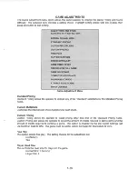
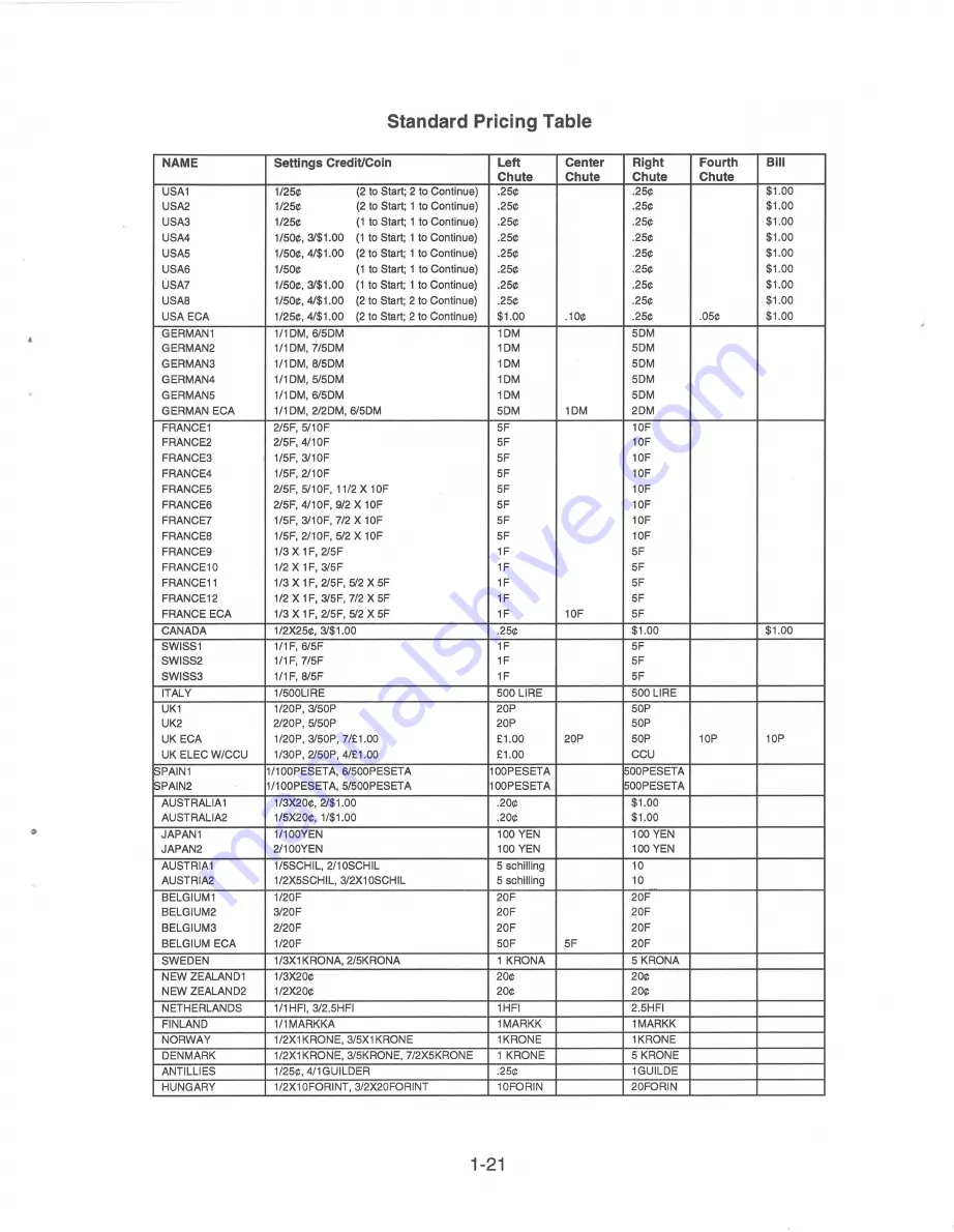
Page 27: ...liers for each chute Custom Pricing Custom Pricing allows the operator to install pricing other than that of the Standard Pricing Table Custom Pricing also allows the operator to select the amount of credits required to start a game and the amount of credits required to continue a game This option is enabled via the Dip Switch Settings set Dip Switch 2 SW8 to ON The game must be set for CMOS Coina...

Page 28: ...imum Setting 16 Factory Setting 8 Game Win Bonus Allows the winning team to play the next game for free Only the challenging team pays On factory Off Computer Assistance When enabled computer keeps game scoring close Factory Setting Enabled Tournament Mode When in Tournament Mode CPU assistance is turned off and no power ups or special guests are allowed No Cheating Factory Setting Disabled Attrac...

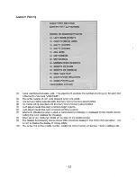
Page 29: ... SF 1F SF FRANCE10 1 2 X 1F 3 SF 1F SF FRANCE11 1 3 X 1F 2 SF 5 2 X SF 1F SF FRANCE12 1 2 X 1F 3 SF 7 2 X SF 1F SF FRANCE ECA 1 3 X 1F 2 SF 5 2 X SF 1F 10F SF CANADA 1 2X2S 3 1 00 2S 1 00 1 00 SWISS1 1 1 F 6 SF 1F SF SWISS2 1 1 F 7 SF 1F SF SWISS3 1 1 F 8 SF 1F SF ITALY 1 SOOLIRE SOO LIRE SOO LIRE UK1 1 20P 3 SOP 20P SOP UK2 2 20P S SOP 20P SOP UK ECA 1 20P 3 SOP 7 1 00 1 00 20P SOP 10P 10P UK ELE...

Page 30: ...Each player needs this many credits to begin a game 6 Each player needs this many credits to continue a game 7 Whenever standard pricing is used a corresponding message is displayed on the credits screen Setting this to no disables the message 8 When set to yes fractional credits will be seen on the credits screen 9 The detailed bookkeeping screen shows total collections based on this many coins p...

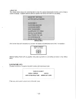
Page 31: ...en activated you are given the option of resetting that item or not For example CLEAR CREDITS ARE YOU SURE m LE J Highlight setting choice with any joystick then press any button to lock setting and return to the Utilities Menu HARDWARE INFO Displays the name of the game the serial number and manufacture date NBA HANGTIME SERIAL NUMBER xxxxxx DATE OF MANUFACTURE MONTH DAY YEAR Press any control pa...

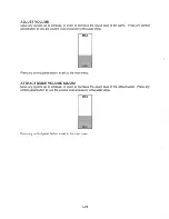
Page 32: ...and return to the Main Menu MAX Press any control panel button to exit to the main menu ATTRACT MODE VOLUME ADJUST Move any joystick up to increase or down to decrease the sound level in the Attract Mode Press any control panel button to lock the volume level and return to the Main Menu MAX Press any control panel button to exit to the main menu 1 24 ...

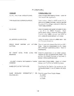
Page 33: ...on JAMMA cable Use pin e as ground reference PRESS START BUTTON AND NOTHING Check for open wires between the button and CPU HAPPENS Board Check for contamination on CPU Board pins or the button switch blade contacts Check for proper ground NO CREDIT GIVEN WHEN COINS ARE Check for contamination on coin switch contacts INSERTED Check for an open wire between Coin Switch 1 and pin 16 on the JAMMA Con...

Page 34: ...Notes 1 26 ...

Page 35: ......

Page 36: ......

Page 37: ...NBA HANGTIME Parts Information 2 1 SECTION TWO ...

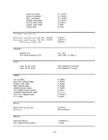
Page 38: ...V Bezel 2511 CRT Instruction Card Coin Meter w Diode PC Boards CPU Final Assembly Control Panel Housing Assembly Control Panel Assembly Control Plate Assembly T Molding Black Control Panel Wood Control Panel Housing Wood Overlay Clear Overlay Screened Red 8 way Joystick Red Blue 8 way Joystick Blue Control Panel Z Bracket Security Latch Bracket 2 2 04 10158 04 10150 03 8326 01 9155 08 7377 H 18610...

Page 39: ... Door Interlock Cable Control Panel Cable Main Harness Cable Cabinet Speaker Cable Line Voltage Cable Assembly Dixie Mars Interconnect Cable USA D B V Adapter Cable ACY Cable Monitor Monitor Mounting Bracket 2511 Monitor Manuals Instruction Manual DBV Installation Instructions 2 3 20 10209 1 20 10209 2 20 10209 3 20 10209 7 20 9275 2 20 9841 1 20 9347 A 20277 A 20277 1 24 8809 01 11262 5555 13961 ...

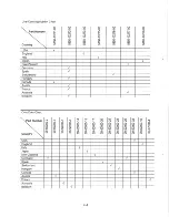
Page 40: ... Hungary Canada Austria France Australia Belgium Coin Door Chart Part Number N I co r LO r 0 N I LO I 0 1 I I I I T T T N N N N I T 0 0 0 0 I I I I I I I I I 0 0 0 0 0 0 0 0 0 0 0 0 0 0 0 0 0 0 0 0 0 0 0 0 0 0 0 0 0 0 0 0 0 0 0 0 0 0 0 0 0 0 r LO LO LO LO 0 0 0 0 0 0 0 0 0 ClO I I I I LO LO LO LO LO LO LO LO ClO I en en en en I I I I I I I I I en 0 0 0 0 en en en en en en en en en 0 Country 0 0 0 ...

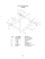
Page 41: ...01123 20B 4420 01141 00 04 10149 1 20 10187 01 8989 01 11285 01 7264 01 11291 4608 01081 11 03 7620 2 5 DESCRIPTION Bolt 1 4 x 1 1 4 CB Nut 1 4 20 Flangegrip Wood Rear Door Cam Lock Cam Lock Plate Plate Lock Retainer Door Bracket H F 8 32 x 11 16 PL HWH Cover Venthole 20 ...

Page 42: ...Switching Power Supply 20 10167 PIN WIRE COLOR 2 3 5 voe RED o o o 3 5 6 GND BLACK o o o 6 7 5V YELLOW TYP O O O g 8 12V ORANGE TYP 9 l 2V BLUE TYP 2 6 ...

Page 43: ... DD DD DD D D DD DD DD DD DD DD DD D D DD DD DD D D DD DD DD DD DD DD DD D D DD DD DD D D DD DD DD DD DD DD DD D D DD DD DD D D DD DD DD DD DD DD DD D D DD DD DD D D DD DD DD D D DD DD DD us D D U2 DD U3 DD U4 DD D D DD u12sn DD DD U116n DD U OBn D D Ul 32 U 24 Ul 20 Ul 12 U 04 D D DD DD DD DD DD DD DD D D DD DD DD D D DD DD DD DD DD DD DD D D DD DD DD D D DD DD DD DD DD DD DD D D DD DD DD D D DD ...

Page 44: ...RDM NBA GAME IMAGE U126 1 A 5343 40059 15 ASSY EPRDM NBA GAME IMAGE U127 1 A 5343 40059 16 ASSY EPRDM NBA GAME IMAGE U128 1 A 5343 40059 17 ASSY EPROM NBA GAME IMAGE U129 1 A 5343 40059 18 ASSY EPROM NBA GAME IMAGE U130 1 A 5343 40059 19 ASSY EPRDM NBA GAME IMAGE Ul 31 1 A 5343 40059 20 ASSY EPROM NBA GAME IMAGE U132 1 A 5343 40059 21 ASSY EPROM NBA GAME IMAGE Ul33 1 A 5343 40059 28 ASSY EPROM NBA...

Page 45: ......

Page 46: ......

Page 47: ...NBA HANGTIME Cabinet Wiring SECTION THREE PRINTED CIRCUIT BOARD ASSEMBLY SCHEMATICS ARE NO LONGER AVAILABLE 3 1 ...

Page 48: ...llow White Video Sync Video Ground Yellow Black 14 R White Gray SeNice Credit Test Black Blue 15 s Black Green Slam Tilt 1 Coin Black Brown 16 T Black Red 2 Coin 1 Start White 17 u Violet White 2 Start 1 Up White Black 18 v Violet Black 2 Up 1 Down White Brown 19 w Violet Brown 2 Down 1 Left White Red 20 x Violet Red 2 Left 1 Right White Orange 21 y Violet Orange 2 Right 1 Shoot Block White Yellow...

Page 49: ...ONING BLOCK I 3 p WHT WHT BU BU 1 1 BU CRN YEl 2 2 J BLK WHT J 4 BU NC BLK 5 0 1 1 6 WHT CRN Y L 7 WHT WHT 7 3 Ylffi ___ 8 9 WHT BLK 1 ___CRN YD 2 WHT 3 BlJ i I 0 Im CRN YD VllEO m o MONTOR mWHT Tl JJ Oc JJ en BU JJ m JJ m GRN YEl POWER zSUPPLY i C YIHT Tl r r e c C m BU 0 C i v I JJ z CRN YEl illo JJ WHT m s zo i i BU GRN YE 2 WHT 3 NC 0 4 r LICHT I 0 s en f lXTURE U E i i ___ OI en 0 oZ I en N E...

Page 50: ...for SI and White for 12Volts This is acceptable oslongosthe pinoutiscorrect MAIN HARNESS CABLE H 20262 FOR OPTIONAL BILL ACCEPTOR ELECTRONIC COIN ACCEPTOR OR ETC COIN CHUTE UGHTS 2 j 111 _ ______ ___L _ _ r 1 TO MONITOR MONITOR TD COIN METER OPTIONAL SECOND COIN METER NBA HANGTIME 40059 WIRING DIAGRAM 5 FULL RANGE 5 FULL RANGE J s z e D z C c C D s ...

Page 51: ......
Page 52: ... at his or her own expense will be required to take whatever measures may be needed to correct the interference Warning Prevent shock hazard and assure proper game operation Only plug this game into a properly grounded outlet Do not use a cheater plug to defeat the power cord s grounding pin Do not cut off the ground pin Notice When MIDWAY ships a game it is in compliance with FCC regulations Your...

Reviews: