1-7
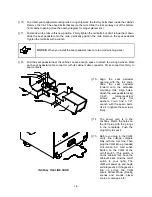
[ ] 16. Unlock and open the coin door. Locate the control switches. Press TEST MODE to enter the
Menu System.
[ ] 17. Select “DISK TESTS” at the Diagnostics Menu. Run all the tests in order to verify correct drive
operation.
[ ] 18. Select “SWITCH TESTS” at the Diagnostics Menu. Check to be sure that all control switches
work.
[ ] 19. Select “SOUND TESTS” at the Diagnostics Menu. Verify operation of each speaker.
[ ] 20. Select “FORCE FEEDBACK TESTS” at the Diagnostics Menu. Verify the presence of steering
resistance.
[ ] 21. Select “CALIBRATE CONTROLS” at the Main Menu. Set steering and throttle limits for maximum
accuracy.
[ ] 22. Select “START THE GAME” at the Main Menu. The system should enter Attract Mode. Open the
coin door and press the SERVICE CREDITS button to allow game play. Press the START button
to begin play. Listen to the audio while playing the game. Note sound irregularities (phase
problems, no low frequencies, mono audio from stereo speakers, etc.). If necessary, check the
wiring harness for internal shorts or strapped connections.
[ ] 23. Change the volume and make adjustments as necessary. Close and lock all open doors. Tighten
the leveler nuts. Engage the caster locks.
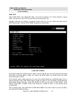
LINKED OPERATION
Equipment Requirements
Linked Mode permits players to compete between networked cabinets in real time. The linking program is
player selectable, so that each cabinet serves player needs.
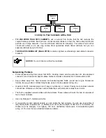
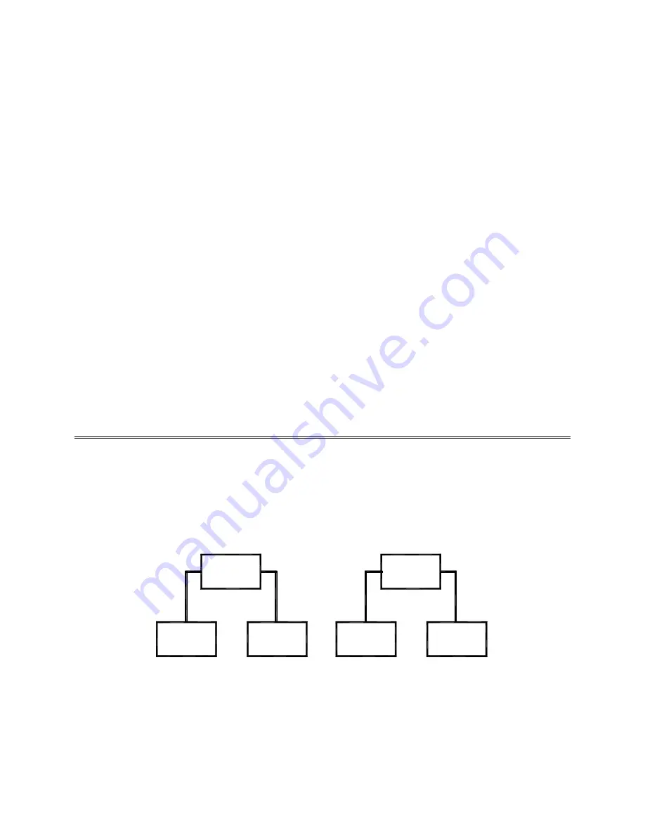
To achieve linked operation, you must connect cabinets. The factory installs one linking cable in each
cabinet.
Coupler
Cabinet
1
Cabinet
2
Cabinet
Cabinet
3
4
Coupler
Link Two Cabinets with a Coupler
•
TO LINK TWO CABINETS, use a crossover coupler. All cabinets contain a crossover coupler to
connect two cabinets together. Use only one coupler between each pair of cabinets. The coupler
employs passive electronics. Passive electronics limit the cable length and number of cabinets that
you can link. Most operations attach linked cabinets, but you can separate cabinets by up to 25 feet.
You can add linked cabinet pairs as necessary.
Summary of Contents for Offroad Thunder
Page 3: ...iii...
Page 4: ...iv...
Page 20: ...Operation 2 6 NOTES...
Page 60: ...Diagnostic Audit Adjustment Menu System 3 40 NOTES...
Page 63: ...Wiring Circuit Information 4 3 Power Wiring Diagram...
Page 64: ...Wiring Circuit Information 4 4 Cabinet Wiring Diagram...
Page 65: ...Wiring Circuit Information 4 5 Player Panel Wiring Diagram...
Page 71: ...Wiring Circuit Information 4 11 BB12 Audio Amplifier Board Schematic 1 4...
Page 72: ...Wiring Circuit Information 4 12 BB12 Audio Amplifier Board Schematic 2 4...
Page 73: ...Wiring Circuit Information 4 13 BB12 Audio Amplifier Board Schematic 3 4...
Page 74: ...Wiring Circuit Information 4 14 BB12 Audio Amplifier Board Schematic 4 4...
Page 79: ...Wiring Circuit Information 4 19 Wheel Driver Board Schematic 1 8...
Page 80: ...Wiring Circuit Information 4 20 Wheel Driver Board Schematic 2 8...
Page 81: ...Wiring Circuit Information 4 21 Wheel Driver Board Schematic 3 8...
Page 82: ...Wiring Circuit Information 4 22 Wheel Driver Board Schematic 4 8...
Page 83: ...Wiring Circuit Information 4 23 Wheel Driver Board Schematic 5 8...
Page 84: ...Wiring Circuit Information 4 24 Wheel Driver Board Schematic 6 8...
Page 85: ...Wiring Circuit Information 4 25 Wheel Driver Board Schematic 7 8...
Page 86: ...Wiring Circuit Information 4 26 Wheel Driver Board Schematic 8 8...
Page 99: ...Parts 7 3 Cabinet Rear View 01 10714 03 8326...
Page 101: ...Parts 7 5 Casters and Levelers...
Page 102: ...Parts 7 6 Rear Casters...
Page 105: ...Parts 7 9 Padlock 4320 01164 20B 01 11287 01 11286 4420 01141 00...
Page 106: ...Parts 7 10 Coin Door Assembly See Coin Door Application Table for Assembly Number...
Page 107: ...Parts 7 11 Pushbutton Assembly 20 9663 XX 20 10129 5 24 8880 24 8828...
Page 110: ...Parts 7 14 Optional Bill Validator...
Page 111: ...Parts 7 15 Cabinet Components...
Page 113: ...Parts 7 17 Casters and Leg Levelers...
Page 114: ...Parts 7 18 Throttle Assembly 20 10135 5014 12909 00...
Page 115: ...Parts 7 19 Fluorescent Lamp Assembly A 22506 20 10444 04 11241 1 24 8809 20 10481 2...
Page 117: ...Parts 7 21 Arcade Computer Mechanical Components...
Page 131: ...Parts 7 35 Line Cord Installation Bracket AC Plug Assembly A 23089...
Page 149: ......


