Troubleshooting 6-4
VGM Startup Troubleshooting Table, continued
SYMPTOM
CAUSE
REQUIRED ACTION
Power problem
1. Inspect circuit boards under low-light conditions.
LEDs glow if processor circuits receive voltage.
Fan should be turning. These indications prove
presence of DC from power supply. Still,
voltages or signals may not be normal.
Computer has no internal LEDs.
2. Turn on VGM power. Using 20-volt DC setting on
digital voltmeter, measure DC voltages at power
connector pins. (Power supply voltage isn’t
adjustable.)
3. Using 2-volt AC setting on digital voltmeter,
measure same DC voltages as above. Any
reading here indicates that supply voltages are
unstable and may contain ripple or noise.
Faulty wiring
Turn off VGM power. Assure that wiring harness
connectors fully seat onto mating board
connectors. Verify that harness connects to
computer. Check other connectors in same way.
Improper jumper or
DIP switch settings
Verify that circuit board jumpers are set as
intended. Check DIP switch settings.
•
VGM
(video game machine)
appears non-functional.
•
Currency acceptor price
indicator is illuminated.
Faulty circuit boards
or arcade computer
1. Run power-up self-test sequence. Note errors or
failures during tests. Compare LEDs with LED
indicator status charts. Note discrepancies.
2. Turn off computer. Wait for hard disk to stop
spinning. Leave VGM power on. Loosen
computer case thumbscrews and lift off cover.
Turn computer power on. Listen for beeping
sounds. Compare beeps with Error Message
Troubleshooting Table.
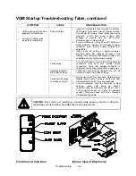
CAUTION: Don’t remove or install any connector while power is turned on. Doing so
will damage circuit boards or hard disk drive, and void warranty.
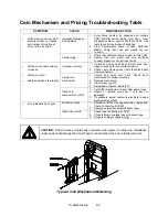
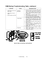
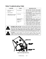
Front View of Coin Door
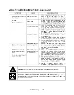
Interior View of Electronics
Summary of Contents for Offroad Thunder
Page 3: ...iii...
Page 4: ...iv...
Page 20: ...Operation 2 6 NOTES...
Page 60: ...Diagnostic Audit Adjustment Menu System 3 40 NOTES...
Page 63: ...Wiring Circuit Information 4 3 Power Wiring Diagram...
Page 64: ...Wiring Circuit Information 4 4 Cabinet Wiring Diagram...
Page 65: ...Wiring Circuit Information 4 5 Player Panel Wiring Diagram...
Page 71: ...Wiring Circuit Information 4 11 BB12 Audio Amplifier Board Schematic 1 4...
Page 72: ...Wiring Circuit Information 4 12 BB12 Audio Amplifier Board Schematic 2 4...
Page 73: ...Wiring Circuit Information 4 13 BB12 Audio Amplifier Board Schematic 3 4...
Page 74: ...Wiring Circuit Information 4 14 BB12 Audio Amplifier Board Schematic 4 4...
Page 79: ...Wiring Circuit Information 4 19 Wheel Driver Board Schematic 1 8...
Page 80: ...Wiring Circuit Information 4 20 Wheel Driver Board Schematic 2 8...
Page 81: ...Wiring Circuit Information 4 21 Wheel Driver Board Schematic 3 8...
Page 82: ...Wiring Circuit Information 4 22 Wheel Driver Board Schematic 4 8...
Page 83: ...Wiring Circuit Information 4 23 Wheel Driver Board Schematic 5 8...
Page 84: ...Wiring Circuit Information 4 24 Wheel Driver Board Schematic 6 8...
Page 85: ...Wiring Circuit Information 4 25 Wheel Driver Board Schematic 7 8...
Page 86: ...Wiring Circuit Information 4 26 Wheel Driver Board Schematic 8 8...
Page 99: ...Parts 7 3 Cabinet Rear View 01 10714 03 8326...
Page 101: ...Parts 7 5 Casters and Levelers...
Page 102: ...Parts 7 6 Rear Casters...
Page 105: ...Parts 7 9 Padlock 4320 01164 20B 01 11287 01 11286 4420 01141 00...
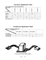
Page 106: ...Parts 7 10 Coin Door Assembly See Coin Door Application Table for Assembly Number...
Page 107: ...Parts 7 11 Pushbutton Assembly 20 9663 XX 20 10129 5 24 8880 24 8828...
Page 110: ...Parts 7 14 Optional Bill Validator...
Page 111: ...Parts 7 15 Cabinet Components...
Page 113: ...Parts 7 17 Casters and Leg Levelers...
Page 114: ...Parts 7 18 Throttle Assembly 20 10135 5014 12909 00...
Page 115: ...Parts 7 19 Fluorescent Lamp Assembly A 22506 20 10444 04 11241 1 24 8809 20 10481 2...
Page 117: ...Parts 7 21 Arcade Computer Mechanical Components...
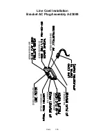
Page 131: ...Parts 7 35 Line Cord Installation Bracket AC Plug Assembly A 23089...
Page 149: ......

