Troubleshooting 6-5
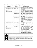
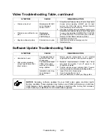
VGM Startup Troubleshooting Table, continued
SYMPTOM
CAUSE
REQUIRED ACTION
Faulty coin
mechanism
1. Unlock and open coin door. Check each
currency acceptor to assure proper mounting.
Verify that each release latch is closed and
locked. Does mechanism accept and reject
currency correctly? Test mechanism with good
and bad coins.
2. Inspect to see if external acceptor indicators
(Pricing, Flashing Arrows, etc.) are lit.
3. Verify that each acceptor operates properly by
placing it in working VGM. Replace bad parts.
Faulty switches
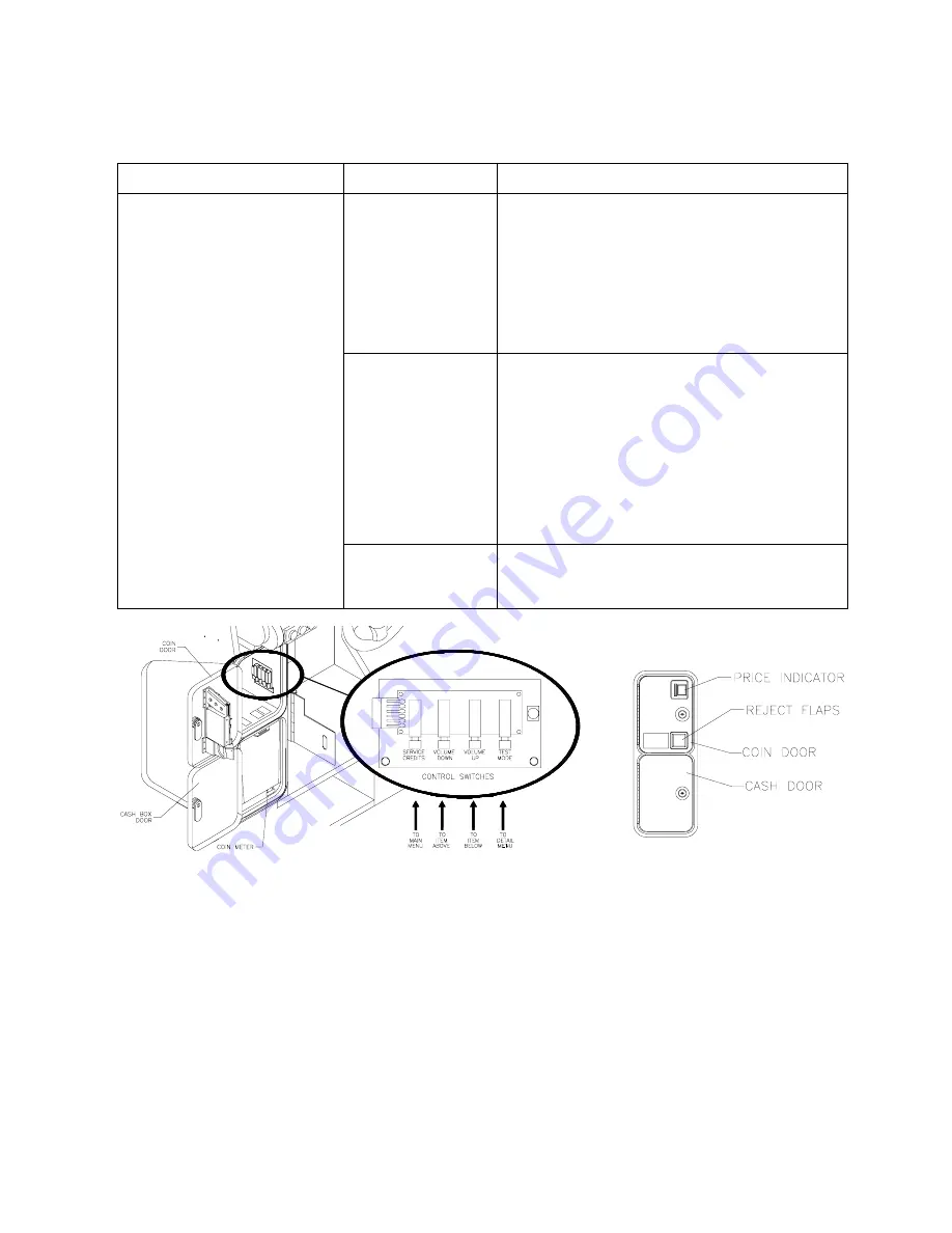
1. Enter Menu System by pressing and holding
TEST MODE switch inside coin door. From
Diagnostics Menu, choose SWITCH AND LAMP
TESTS. Use tests to confirm operation of each
switch in VGM.
2. Assure that no loose parts or wires are caught in
switch contacts.
3. Check for continuity in each suspect switch
connection (Common to Normally Open or
Common to Normally Closed).
4. Replace faulty switches (bent levers, broken
actuators, etc.).
•
VGM
(video game machine)
doesn’t start.
•
VGM accepts currency or
tokens.
•
Audio and video are present.
Faulty wiring
1. Assure that no wires are caught in hinges,
latches or switch contacts.
2. Check wiring continuity from circuit board
connectors to acceptors.
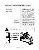
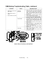
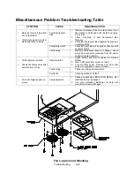
Interior View of Coin Door and Cash Door
Summary of Contents for Offroad Thunder
Page 3: ...iii...
Page 4: ...iv...
Page 20: ...Operation 2 6 NOTES...
Page 60: ...Diagnostic Audit Adjustment Menu System 3 40 NOTES...
Page 63: ...Wiring Circuit Information 4 3 Power Wiring Diagram...
Page 64: ...Wiring Circuit Information 4 4 Cabinet Wiring Diagram...
Page 65: ...Wiring Circuit Information 4 5 Player Panel Wiring Diagram...
Page 71: ...Wiring Circuit Information 4 11 BB12 Audio Amplifier Board Schematic 1 4...
Page 72: ...Wiring Circuit Information 4 12 BB12 Audio Amplifier Board Schematic 2 4...
Page 73: ...Wiring Circuit Information 4 13 BB12 Audio Amplifier Board Schematic 3 4...
Page 74: ...Wiring Circuit Information 4 14 BB12 Audio Amplifier Board Schematic 4 4...
Page 79: ...Wiring Circuit Information 4 19 Wheel Driver Board Schematic 1 8...
Page 80: ...Wiring Circuit Information 4 20 Wheel Driver Board Schematic 2 8...
Page 81: ...Wiring Circuit Information 4 21 Wheel Driver Board Schematic 3 8...
Page 82: ...Wiring Circuit Information 4 22 Wheel Driver Board Schematic 4 8...
Page 83: ...Wiring Circuit Information 4 23 Wheel Driver Board Schematic 5 8...
Page 84: ...Wiring Circuit Information 4 24 Wheel Driver Board Schematic 6 8...
Page 85: ...Wiring Circuit Information 4 25 Wheel Driver Board Schematic 7 8...
Page 86: ...Wiring Circuit Information 4 26 Wheel Driver Board Schematic 8 8...
Page 99: ...Parts 7 3 Cabinet Rear View 01 10714 03 8326...
Page 101: ...Parts 7 5 Casters and Levelers...
Page 102: ...Parts 7 6 Rear Casters...
Page 105: ...Parts 7 9 Padlock 4320 01164 20B 01 11287 01 11286 4420 01141 00...
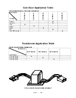
Page 106: ...Parts 7 10 Coin Door Assembly See Coin Door Application Table for Assembly Number...
Page 107: ...Parts 7 11 Pushbutton Assembly 20 9663 XX 20 10129 5 24 8880 24 8828...
Page 110: ...Parts 7 14 Optional Bill Validator...
Page 111: ...Parts 7 15 Cabinet Components...
Page 113: ...Parts 7 17 Casters and Leg Levelers...
Page 114: ...Parts 7 18 Throttle Assembly 20 10135 5014 12909 00...
Page 115: ...Parts 7 19 Fluorescent Lamp Assembly A 22506 20 10444 04 11241 1 24 8809 20 10481 2...
Page 117: ...Parts 7 21 Arcade Computer Mechanical Components...
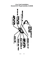
Page 131: ...Parts 7 35 Line Cord Installation Bracket AC Plug Assembly A 23089...
Page 149: ......

