Setup 1-3
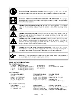
WARNING: AVOID ELECTRICAL SHOCKS. This video game machine does not utilize
an isolation transformer. Internal, cabinet AC isn’t isolated from the external, AC line.
WARNING: HANDLE FLUORESCENT TUBE AND CRT WITH CARE. If you drop a
fluorescent tube or CRT and it breaks, it will implode! Shattered glass can fly eight feet
or more from the implosion.
CAUTION: CHECK POWER SELECTOR. Set the 110/220VAC selector on the power
supply for the correct line voltage. Check the selector setting before switching on the
VGM.
CAUTION: USE PROPER FUSE. Avoid electrical shock! Replacement fuses must be
of the same type as those they replace. Fuse voltage and current ratings must match
ratings on the original fuse.
CAUTION: ATTACH CONNECTORS PROPERLY. Be sure that printed circuit board
(PCB) connectors mate properly. If connectors don’t slip on easily, don’t force them. A
reversed connector may damage your VGM and void the warranty. Connector keys only
allow a connector to fit one set of pins on a board.
CAUTION: TAKE CARE WHEN SHIPPING HARD DISKS. The hard disk drive must be
packed in an anti-static bag. When shipping the drive for repair or replacement, pack it
in an approved container (P/N 08-8068). Never stack or drop hard disk drives.
NOTICE:
This manual is subject to change without notice. Midway reserves the right to make
equipment improvements as engineering progress warrants.
PRODUCT SPECIFICATIONS
Operating Requirements
Location
Domestic
Foreign
Japan
Electrical Power
120VAC @ 60Hz 4.0 Amps
230VAC @ 50Hz 2.0 Amps
100VAC @ 50Hz 4.0 Amps
Temperature
32°F to 100°F
(0°C to 38°C)
Humidity
Not to exceed 95% relative
Cabinet Statistics
Shipping Dimensions
Cabinet
Shipping Dimensions
Seat Pedestal
Shipping Weight
Cabinet
Boxed, 360 lbs. (163 kg.)
Seat pedestal
Width
Depth
Height
32.0" (81.3 cm)
42" (169 cm)
76.0" (193 cm)
Width
Depth
Height
22.0” (55.8 cm)
36.0” (91.4 cm)
51.0” (130 cm)
Boxed, 125 lbs. (56.8 kg.)
Equipment Characteristics
Video Monitor
Medium Resolution RGB
27” (63.5 cm) CRT
Audio System
Digital Stereo Sound
Two 5.5” (14 cm) and
One 6.5” (16.5 cm) Spkr
Currency Acceptors
2 Coin Mechanism, Coin Counter
Dollar Bill Validator Ready
Electronic Coin Acceptor Ready
Summary of Contents for Offroad Thunder
Page 3: ...iii...
Page 4: ...iv...
Page 20: ...Operation 2 6 NOTES...
Page 60: ...Diagnostic Audit Adjustment Menu System 3 40 NOTES...
Page 63: ...Wiring Circuit Information 4 3 Power Wiring Diagram...
Page 64: ...Wiring Circuit Information 4 4 Cabinet Wiring Diagram...
Page 65: ...Wiring Circuit Information 4 5 Player Panel Wiring Diagram...
Page 71: ...Wiring Circuit Information 4 11 BB12 Audio Amplifier Board Schematic 1 4...
Page 72: ...Wiring Circuit Information 4 12 BB12 Audio Amplifier Board Schematic 2 4...
Page 73: ...Wiring Circuit Information 4 13 BB12 Audio Amplifier Board Schematic 3 4...
Page 74: ...Wiring Circuit Information 4 14 BB12 Audio Amplifier Board Schematic 4 4...
Page 79: ...Wiring Circuit Information 4 19 Wheel Driver Board Schematic 1 8...
Page 80: ...Wiring Circuit Information 4 20 Wheel Driver Board Schematic 2 8...
Page 81: ...Wiring Circuit Information 4 21 Wheel Driver Board Schematic 3 8...
Page 82: ...Wiring Circuit Information 4 22 Wheel Driver Board Schematic 4 8...
Page 83: ...Wiring Circuit Information 4 23 Wheel Driver Board Schematic 5 8...
Page 84: ...Wiring Circuit Information 4 24 Wheel Driver Board Schematic 6 8...
Page 85: ...Wiring Circuit Information 4 25 Wheel Driver Board Schematic 7 8...
Page 86: ...Wiring Circuit Information 4 26 Wheel Driver Board Schematic 8 8...
Page 99: ...Parts 7 3 Cabinet Rear View 01 10714 03 8326...
Page 101: ...Parts 7 5 Casters and Levelers...
Page 102: ...Parts 7 6 Rear Casters...
Page 105: ...Parts 7 9 Padlock 4320 01164 20B 01 11287 01 11286 4420 01141 00...
Page 106: ...Parts 7 10 Coin Door Assembly See Coin Door Application Table for Assembly Number...
Page 107: ...Parts 7 11 Pushbutton Assembly 20 9663 XX 20 10129 5 24 8880 24 8828...
Page 110: ...Parts 7 14 Optional Bill Validator...
Page 111: ...Parts 7 15 Cabinet Components...
Page 113: ...Parts 7 17 Casters and Leg Levelers...
Page 114: ...Parts 7 18 Throttle Assembly 20 10135 5014 12909 00...
Page 115: ...Parts 7 19 Fluorescent Lamp Assembly A 22506 20 10444 04 11241 1 24 8809 20 10481 2...
Page 117: ...Parts 7 21 Arcade Computer Mechanical Components...
Page 131: ...Parts 7 35 Line Cord Installation Bracket AC Plug Assembly A 23089...
Page 149: ......


