background image

Servicing

          5-1

O

O

O

O

FFROAD

FFROAD

FFROAD

FFROAD

THUNDER

THUNDER

THUNDER

THUNDER


TM

CHAPTER

5

SERVICING

NOTICE: 

The term VGM refers to the video game machine.

NOTICE: 

Avoid damage to electronics! Turn off VGM power before servicing circuit

boards or any electronic assembly. Never “hot plug” circuit boards.

CAUTION:

 Static electricity builds up on your body. This static can damage or destroy

sensitive circuits. 

Before

 touching or handling electronics, discharge static electricity by

touching the power supply chassis.

Summary of Contents for Offroad Thunder

Page 1: ...Sit In Dedicated 27 Video Game Operation Manual 1 Setup 2 Operation 3 Audits 4 Wiring 5 Servicing 6 Troubleshooting 7 Parts Midway Games Inc 3401 North California Avenue Chicago Illinois 60618 5899 U...

Page 2: ...rear of the cabinets Connect all linking cables When you use a hub don t use any couplers 4 Turn on cabinet power ADJUST GAME OPTIONS CAUTION Don t connect or disconnect cables to the game electronic...

Page 3: ...iii...

Page 4: ...iv...

Page 5: ...on Card Include the product serial number from the label on the rear of the cabinet For your records write the product serial number in the manual SERIAL NUMBER _______________________________________...

Page 6: ...s with power ON can damage components and void the warranty Be sure that you securely install ground wires WARNING GROUND VGMS Avoid electrical shocks Don t plug in a VGM until you have inspected and...

Page 7: ...t of pins on a board CAUTION TAKE CARE WHEN SHIPPING HARD DISKS The hard disk drive must be packed in an anti static bag When shipping the drive for repair or replacement pack it in an approved contai...

Page 8: ...arts 1 Remove and set aside items from the shipping containers Remove all packing material Inspect for damage Check the main cabinet exterior the control section and the seat pedestal 2 Remove the key...

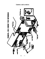
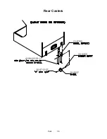
Page 9: ...e seat pedestal uses three Place the swivel caster in front Place two locking casters in back Tighten the caster mounting nuts very firmly INSTALL CASTERS AND LEVELERS 8 Stand the cabinet upright and...

Page 10: ...ctor Press connectors firmly to seat contacts 13 Align the seat pedestal opening with the rail ends Slide the seat pedestal forward onto the extended mounting rails Align holes Attach the seat pedesta...

Page 11: ...mono audio from stereo speakers etc If necessary check the wiring harness for internal shorts or strapped connections 23 Change the volume and make adjustments as necessary Close and lock all open do...

Page 12: ...roved conduit or wire channels to support cables Network modular connectors don t include strain relief Keep cables away from heat moisture and electromagnetic fields Avoid neon signs fluorescent fixt...

Page 13: ...power adapter into its jack on the hub 10 Set the hub front panel switch to the LNK link position 11 Retract excess cable into the cabinet coils so that the cables don t touch the floor Retracting th...

Page 14: ...e Linked Play Adjustments Menu 5 LINKED PLAY At each cabinet set the LINKED PLAY option to YES 6 UNIT ID Each cabinet must have a unique unit ID Set the option UNIT ID to a separate number for each ca...

Page 15: ...Operation 2 1 2 52 7 81 5 TM 37 5 OPERATION NOTICE The term VGM refers to the video game machine...

Page 16: ...e access without sacrificing ruggedness or reliability PLAYER CONTROLS ACCELERATOR The accelerator pedal controls vehicle speed and acceleration BRAKE The brake pedal stops the vehicle just like a rea...

Page 17: ...leave this switch on Use the main power switch to control the power DIAGNOSTIC CONTROL SWITCHES The SERVICE CREDITS Button allots credits without changing the game s bookkeeping total The Menu System...

Page 18: ...truck on any course Each truck handles and performs differently Players learn which trucks are best for a given course and driving style Press one of the CAM buttons to select more trucks CONTROLLING...

Page 19: ...CING Networked cabinets offer players linked head to head racing competition Each player begins the course selection process A join in message alerts subsequent players to the possibility of a linked...

Page 20: ...Operation 2 6 NOTES...

Page 21: ...System 3 1 2 52 7 81 5 TM 37 5 DIAGNOSTIC AUDIT ADJUSTMENT MENU SYSTEM NOTICE Information in this manual is subject to change without notice Midway reserves the right to make improvements in equipmen...

Page 22: ...SYSTEM Open the coin door Find the TEST MODE switch inside Press TEST MODE to invoke the Menu System The game system responds by exiting Game Mode and entering Diagnostic Mode The system runs a brief...

Page 23: ...menu that allows you to exit the Menu System EQUIVALENT MENU NAVIGATION CONTROLS In most cases certain player panel buttons duplicate the functions of the diagnostic buttons You may find menu navigat...

Page 24: ...Operator Menu The Diagnostics Menu helps you to verify the electrical and electronic condition of the game Highlight a line item with the middle two diagnostic buttons inside the coin door Select the...

Page 25: ...Gray means off and green means on Release the button and the indicator returns to its previous state A single indication on the screen should exactly duplicate each button change THE WHEEL TEST indica...

Page 26: ...on of game lamps These include lamps in the control panel and overhead linking sign or optional header Unless your cabinet has header lights the Leader Upper and Leader Lower tests have no effect For...

Page 27: ...empting monitor adjustments MONITOR PATTERNS MENU Color Bars paint colored stripes on the screen Use the color bars to help you to check or adjust monitor brightness and contrast The color bars also e...

Page 28: ...er Color Screen tests fill the screen with 100 of the chosen color at normal intensity The Color Screen tests help you to check or adjust monitor intensity black level blanking and color purity Each s...

Page 29: ...crease the master volume level before beginning this test Highlight a test with the middle two diagnostic buttons inside the coin door Select the option with the TEST MODE button Selecting also activa...

Page 30: ...e TEST MODE button GAME AUDITS MENU Use the auditing information to help you to keep records of the game s popularity and earnings You may also analyze favorite tracks most frequently used vehicles an...

Page 31: ...ncy collection The other items present information on game operation BONUS CREDITS A running total of bonus credits that the video game awarded to players GAME IN PROGRESS DURING LAST SHUTDOWN Was the...

Page 32: ...changes Once you ve cleared the counters you can t retrieve the previous data from the system THE COIN COUNT AND BILL COUNT items help you to assess currency collection The other items present inform...

Page 33: ...layers played on this machine CONTINUES Total number of games on this machine that players paid to continue FREE GAMES WON remains at zero if you turn off the bonus and award options Refer to the Gene...

Page 34: ...ayer choices and ability This is a read only menu TYPICAL TRACK AUDITS MENU These audits cover several screen pages The name of the track appears at the top of the page Press the VOLUME UP or VOLUME D...

Page 35: ...t the Audits Menu The Truck Audits Menu gives you specific information about player choices and ability This is a read only menu Menu software includes several pages of audits The name of the vehicle...

Page 36: ...these screens to optimize game performance and earnings Highlight an option with the middle two diagnostic buttons inside the coin door Select the option with the TEST MODE button ADJUSTMENTS MENU GEN...

Page 37: ...JUSTMENTS MENU FREE PLAY determines whether the game accepts money for play or allows operation without charge For free play turn this option on For paid play turn this option off the factory default...

Page 38: ...speed in kilometers per hour turn SHOW MILES PER HOUR off To display speed in miles per hour turn SHOW MILES PER HOUR on the factory default ADULT MODE When you enable Adult Mode the glamorous cheerl...

Page 39: ...NKED PLAY ADJUSTMENTS MENU Before proceeding bring up the Linked Play Adjustments Menu on all linked cabinets LINKED PLAY After you link a cabinet to other games turn on LINKED PLAY Now game electroni...

Page 40: ...ic switches to change the variable Then press TEST MODE to save changes and exit the variable TRACK DIFFICULTY ADJUSTMENTS MENU LIMIT FREE RACES TO LFRT is the award cutoff point LFRT prevents expert...

Page 41: ...TEST MODE to enter Change Mode Use the diagnostic switches to change the variable Press TEST MODE to save changes and exit the variable Or press TEST CREDITS to cancel changes and exit the variable Yo...

Page 42: ...de Use the diagnostic switches to change the variable Then press TEST MODE to save changes and exit the variable Turning on Free Play disables Pricing Menu settings PRICING MENU SELECT CUSTOM PRICING...

Page 43: ...own pricing table You can save several pricing schemes and chose between them as desired Highlight an option with the middle two diagnostic buttons inside the coin door Press TEST MODE to enter Change...

Page 44: ...nd form of cyber currency Even though you ve now bought one game you may not be able to begin playing In many pricing schemes you must buy two or more credits to begin play The idea here is something...

Page 45: ...nt Menu SELECT STANDARD PRICING CONTINENT MENU Choose SELECT STANDARD PRICING at the Pricing Menu The Select Standard Pricing Continent Menu allows you to choose the continent that you are operating i...

Page 46: ...A MENU Choose a continent NORTH AMERICA for example at the Select Standard Pricing Continent Menu The Select Standard Pricing Country for North America Menu contains options for selecting standard cur...

Page 47: ...STANDARD PRICING MENU Suppose that you want to set U S pricing Choose USA at the menu entitled Select Standard Pricing Country for North America This menu contains options for selecting standard U S...

Page 48: ...3 10Fr 1Fr 5Fr 10Fr 20Fr FRANCE ECA 4 1 1 1 5Fr 2 10Fr 1Fr 5Fr 10Fr 20Fr FRANCE ECA 5 1 1 2 5Fr 5 10Fr 11 2 X 10Fr 1Fr 5Fr 10Fr 20Fr FRANCE ECA 6 1 1 2 5Fr 4 10Fr 9 2 X 10Fr 1Fr 5Fr 10Fr 20Fr FRANCE...

Page 49: ...30p 2 50p 4 1 00 1 00 50p 20p 10p 2 00 UK ECA 7 1 1 3 1 00 1 00 50p 20p 10p 2 00 UK ECA 8 1 1 1 50p 2 1 00 4 2 00 1 00 50p 20p 10p 2 00 USA1 2 2 1 25 25 25 1 00 USA2 2 1 1 25 25 25 1 00 USA3 1 1 1 25...

Page 50: ...ss TEST MODE to enter Change Mode Use the diagnostic switches to change the variable Then press TEST MODE to save changes and exit the variable VOLUME ADJUSTMENT MENU NOTICE The Master Volume setting...

Page 51: ...TTRACT VOLUME adjusts the Attract Mode sound level only when you turn on Attract Mode The Attract Mode sound level is independent of game audio levels The Attract Volume range is 1 to 100 The factory...

Page 52: ...tic switches to change the variable Then press TEST MODE to save changes and exit the variable FORCE FEEDBACK ADJUSTMENT MENU THE INTENSITY ADJUSTMENT ranges from 0 minimum to 100 maximum The factory...

Page 53: ...move the game move it before calibrating player control switches To set up each calibration procedure follow screen directions Press TEST MODE to begin the procedure STEERING GAS AND BRAKE CALIBRATIO...

Page 54: ...k adjustments for time zone changes and seasonal time changes Highlight an option with the middle two diagnostic buttons inside the coin door Press TEST MODE to enter Change Mode Use the diagnostic sw...

Page 55: ...e diagnostic switches to change the variable Then press TEST MODE to save changes and exit the variable UTILITIES MENU CLEAR CREDITS zeros all credit variables RESET OPERATOR SETTINGS returns Adjustme...

Page 56: ...es on profits Use a formatted 1 44MB high density diskette The floppy drive is in the CPU cabinet NOTICE Be careful when clearing audit information Once you clear data you can t restore it Use the Sav...

Page 57: ...ST MODE to save changes and exit the variable VOLUME ADJUSTMENT MENU NOTICE The Master Volume setting affects all other volume adjustments You can still alter Attract sounds in relation to normal game...

Page 58: ...e The Attract Mode sound level is independent of game audio levels The Attract Volume range is 1 to 100 The factory default is 50 MINIMUM VOLUME sets the quietest sound level during game play The rang...

Page 59: ...move it before calibrating player control switches To set up each calibration procedure follow screen directions Press TEST MODE to begin the procedure STEERING GAS AND BRAKE CALIBRATION SCREEN The s...

Page 60: ...Diagnostic Audit Adjustment Menu System 3 40 NOTES...

Page 61: ...mation 4 1 2 52 7 81 5 TM 37 5 WIRING CIRCUIT INFORMATION WARNING Failure to reconnect ground wires or replace metal shields may result in radio frequency interference NOTICE The term VGM refers to th...

Page 62: ...6 Video Monitor 6P1 7 Wheel Driver Board 7P1 8 Coin Door Area 8P1 9 BB12 Audio Board 9P1 10 LED Interconnect Board 10P1 11 Cabinet 11P1 12 Optional Overhead Marquee 12P1 13 Dashboard 13P1 14 Gas Peda...

Page 63: ...Wiring Circuit Information 4 3 Power Wiring Diagram...

Page 64: ...Wiring Circuit Information 4 4 Cabinet Wiring Diagram...

Page 65: ...Wiring Circuit Information 4 5 Player Panel Wiring Diagram...

Page 66: ...ature isn t installed 5 Connect processor module fan to this jack Computer may become unreliable if processor overheats 6 Connect processor module to this jack 242 pin socket accepts single microproce...

Page 67: ...3 Expansion Slot Circuit Aux Devices J3F1 Middle Center Chassis Not Used In This Open Near CPU Intrusion VGM No 1 2 Note 4 And Fan Circuit Intrusion J3F2 Middle Center Processor Two Speed Fan Open Nea...

Page 68: ...Off Not In Use No Game Link On Normal Operation Blinking Link Fault Note 1 LED 2 ACT Right Center Under Jack Activity Indicator Green Off Not In Use No Data On Receiving Data Note 2 Blinking Normal O...

Page 69: ...g Setting Default J1 Left Center Video Graphic Open DB 15 on Signal Information 1 15 Note 1 Bracket Output To Interface J2 J7 None Not Used Open Note 2 JP2 None Not Used Open Note 2 Notes 1 Connects t...

Page 70: ...t Indicator Red Off Normal Operation On Locked Up Note 1 Blinking Overload Note 2 LED 2 CR2 Lower Center Near U2 U6 Fault Indicator Red Off Normal Operation On Locked Up Note 1 Blinking Overload Note...

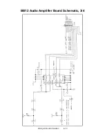
Page 71: ...Wiring Circuit Information 4 11 BB12 Audio Amplifier Board Schematic 1 4...

Page 72: ...Wiring Circuit Information 4 12 BB12 Audio Amplifier Board Schematic 2 4...

Page 73: ...Wiring Circuit Information 4 13 BB12 Audio Amplifier Board Schematic 3 4...

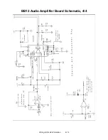
Page 74: ...Wiring Circuit Information 4 14 BB12 Audio Amplifier Board Schematic 4 4...

Page 75: ...enter Near D19 D26 Host Watchdog Reset 2 Off Watchdog Enabled On Watchdog Disabled Notes 1 Bank 1 Switch 8 should be off for Offroad Thunder See the table above 2 Bank 1 Switch 7 should be off for Off...

Page 76: ...Indicator Red On EEPROM not responding Blinking Normal Operation LED 8 Off Not In Use Security Right Center Near DIP Switch S1 Indicator Red On Security error Blinking Normal Operation LED 7 Off Not...

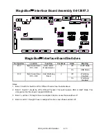
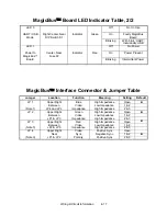
Page 77: ...us Interface Connector Jumper Table Jumper Location Function Meaning Setting Default JP 1 Upper Right Blue High Impedance Open Between Video Low Impedance 1 2 Note 1 JP4 and JP2 Impedance High Impedan...

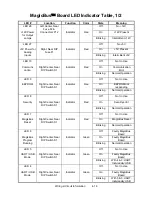
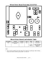
Page 78: ...ion Location Function Color State Meaning LED 1 Right Center Near C5 P2 Indicator Red Off Not In Use On Normal Operation Blinking Power Fault Note 1 Notes 1 LED 1 monitors regulated power supply volta...

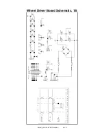
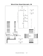
Page 79: ...Wiring Circuit Information 4 19 Wheel Driver Board Schematic 1 8...

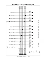
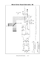
Page 80: ...Wiring Circuit Information 4 20 Wheel Driver Board Schematic 2 8...

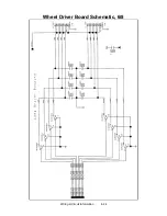
Page 81: ...Wiring Circuit Information 4 21 Wheel Driver Board Schematic 3 8...

Page 82: ...Wiring Circuit Information 4 22 Wheel Driver Board Schematic 4 8...

Page 83: ...Wiring Circuit Information 4 23 Wheel Driver Board Schematic 5 8...

Page 84: ...Wiring Circuit Information 4 24 Wheel Driver Board Schematic 6 8...

Page 85: ...Wiring Circuit Information 4 25 Wheel Driver Board Schematic 7 8...

Page 86: ...Wiring Circuit Information 4 26 Wheel Driver Board Schematic 8 8...

Page 87: ...e NOTICE Avoid damage to electronics Turn off VGM power before servicing circuit boards or any electronic assembly Never hot plug circuit boards CAUTION Static electricity builds up on your body This...

Page 88: ...he connector and other cables Extract the harnesses from the board connectors Remove mounting screws from the Audio Board Lift the board out of the cabinet Handle the board by a heatsink If you aren t...

Page 89: ...meter Assure that the replacement meter has a diode across its terminals This diode protects driver circuits from the meter s inductive kick Install the new meter Log the new meter count Coin Mechanis...

Page 90: ...djustment bolt as necessary Tighten this bolt until the belt is taut Then restore correct tension by loosening the bolt one full turn Tighten the motor bracket nuts DIMMs Dual In Line Memory Modules D...

Page 91: ...stripe lug to the door ground stud The stud is beside the hinge Mate the wiring harnesses and press them together to fully seat connectors Route wires away from the door edges and hinge To remove a v...

Page 92: ...ribbon cable from the floppy drive Leave the other end of the cable attached to the CPU Board Unscrew and remove the circuit board retention bars Remove the drive bracket mounting hardware Remove the...

Page 93: ...drive out of the cabinet Save the mounting screws for reuse in future hard drive installations When returning a hard drive to your distributor pack it in an anti static bag Box the drive in approved s...

Page 94: ...VGM Unlock and remove the rear door From inside the cabinet disconnect the dash cables Remove the top two dashboard mounting screws Remove the dash bracket Slide the viewing glass upward Lift the gla...

Page 95: ...k the line voltage switch setting Speakers This VGM has four speakers One woofer is behind a grille at the back of the driver s seat Smaller full range speakers are behind the marquee A second woofer...

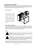
Page 96: ...to store the board if you won t reinstall it Wheel Driver Board Switch off power to the VGM Unlock and open the rear door and the coin door The Wheel Driver Board mounts to the wooden shelf behind th...

Page 97: ...y cause serious injury or equipment damage Use only Midway authorized parts For safety and reliability don t substitute parts or modify Midway products Substitute parts or modifications may void the g...

Page 98: ...Parts 7 2 Cabinet Front View 03 8252 5 08 7980 31 3423 1 2 08 7853 03 9932 1 5675 16273 00 04 12760 1 04 12760 2 23 6723 01 15084 A 22506 31 3418 2 A 23231 31 3423 1 1...

Page 99: ...Parts 7 3 Cabinet Rear View 01 10714 03 8326...

Page 100: ...Parts 7 4 Cabinet Joining Details 4700 00033 00B 4701 00005 00 4320 01124 16 04 10112 4020 01100 20...

Page 101: ...Parts 7 5 Casters and Levelers...

Page 102: ...Parts 7 6 Rear Casters...

Page 103: ...Parts 7 7 Rear Door Assembly A 23238 20 10350 03 7602 01 11291 4320 01164 20B 11 1375 1 01 7264 4108 01219 11 4420 01141 00 01 8989 01 11285 4420 01141 00 4320 01164 20B...

Page 104: ...Parts 7 8 Monitor Bezel Components 03 8252 5 31 3418 2 08 7980 08 7853 03 9932 1 01 15084 4108 01219 11 5555 15098 00 4406 01128 00 4506 01106 24B 4108 01193 10B 01 15083 3...

Page 105: ...Parts 7 9 Padlock 4320 01164 20B 01 11287 01 11286 4420 01141 00...

Page 106: ...Parts 7 10 Coin Door Assembly See Coin Door Application Table for Assembly Number...

Page 107: ...Parts 7 11 Pushbutton Assembly 20 9663 XX 20 10129 5 24 8880 24 8828...

Page 108: ...Parts 7 12 Dash Assembly A 23113 20 9663 22 20 9663 23 20 9663 24 20 10129 5 20 1053 1 03 9933 2 20 10595 20 10494 03 9910 1...

Page 109: ...12729 3 14 8029 04 12730 1 4006 01100 16B 4700 00129 00B 4008 01100 08 04 12784 1 H 23218 4020 01100 20 03 9910 1 20 10189 20 10503 1 02 5351 1 4006 01100 08B 31 3419 1 20 10595 03 9933 2 20 10627 02...

Page 110: ...Parts 7 14 Optional Bill Validator...

Page 111: ...Parts 7 15 Cabinet Components...

Page 112: ...805 04 12705 01 14950 1 04 11293 2 31 3422 5555 16059 00 4020 01148 20 4108 01193 10B 4110 01001 20 01 14497 4108 01193 10B 01 14939 1 RM 37 11 04 10872 4020 01100 08 4702 00014 00B 4700 00072 00 4322...

Page 113: ...Parts 7 17 Casters and Leg Levelers...

Page 114: ...Parts 7 18 Throttle Assembly 20 10135 5014 12909 00...

Page 115: ...Parts 7 19 Fluorescent Lamp Assembly A 22506 20 10444 04 11241 1 24 8809 20 10481 2...

Page 116: ...Parts 7 20 Arcade Computer Assembly A 23253 5795 15344 12 A 23350 04 12687 20 10554 20 10550 04 12651 20 10551 20 10555 20 10552...

Page 117: ...Parts 7 21 Arcade Computer Mechanical Components...

Page 118: ...Parts 7 22 Arcade Computer Cables 20 10554 04 12651 20 10552 04 12657 NOTICE DC power cables are part of the power supply You can t replace these cables individually...

Page 119: ...me machine Operation in this VGM also requires a custom operating system NOTICE Before attempting to use other than factory authorized parts ask your distributor for information Other DIMM and process...

Page 120: ...ard Location Part Number Dual Inline Memory Module 64MB SDRAM DIMM BANK 0 1 2 20 10557 Memory Backup 3 Volt Lithium Battery B 5882 16135 00 Processor Assembly Celeron Processor J4J1 20 10607 Processor...

Page 121: ...Parts 7 25 Network Interface Card Assembly 20 10550 Field Replaceable Parts Component Description Board Location Part Number Instruction ROM Not required in this game U2...

Page 122: ...Parts 7 26 Video Graphics Card Assembly 20 10551 Field Replaceable Parts Component Description Board Location Part Number Graphics Mode Select Not required in this game J6...

Page 123: ...er Filter Board Assembly 04 12651 Field Replaceable Parts Component Description Board Location Part Number EMI Filter 2200 pF Dual Capacitor F1 F5 5060 15633 00 EMI Filter Ferrite Bead Inductor L1 L5...

Page 124: ...cription Board Location Part Number Audio Amplifier LM3403 Quad Amplifier U1 U2 5370 15163 00 Audio Output TDA1560Q Power Amplifier U3 5370 15984 00 Audio Output TDA7375 Power Amplifier U4 5370 15833...

Page 125: ...t Number Crystal 6 MHz Y2 5520 16004 00 Diode 1N270 D11 15 D17 25 D28 5070 16229 00 Diode 1N5817 1A D2 5070 09266 00 Fuse 5 x 20mm 2ASB F1 5735 13853 00 Jumper 2 Pin JP1 JP2 JP3 JP4 5791 13045 00 Tran...

Page 126: ...08976 00 Diode Fast FE6B 35nS D2 D3 5070 16272 00 Driver Power LM12 Op Amplifier U5 5370 14069 00 Fuse 0 63AFB 250V 5x20mm F3 5731 15627 00 Fuse 4ASB 125V 5x20mm F1 F2 5731 14094 00 Pre Driver ULN2064...

Page 127: ...achometer Board Assembly 04 12759 1 Field Replaceable Parts Component Description Board Location Part Number LED Green Bright LED1 6 5671 16256 00 LED Orange Bright LED7 10 5671 15953 00 LED Red Brigh...

Page 128: ...Parts 7 32 Electronic Cable Assemblies SERIAL COMMUNICATIONS CABLE NULL MODEM DB 9F TO DB 9F 20 10532 VIDEO COMMUNICATIONS CABLE SHIELDED DB 15F TO DB 15M 5797 13171 00...

Page 129: ...Parts 7 33 Electronic Cable Assemblies AUDIO AMPLIFIER CABLE SHIELDED MINIATURE STEREO PHONE PLUG TO PHONO PLUGS 04 12578 2 COMPUTER RESET CABLE 2 PIN PLUG TO LOCKING 2 PIN PLUG 04 12657...

Page 130: ...Parts 7 34 Line Cord Application Table Part Number Country 5850 13271 00 5850 15521 00 5850 15521 02 5850 15521 03 5850 15521 06 France Germany Italy Japan Spain UK USA TYPICAL LINE CORD...

Page 131: ...Parts 7 35 Line Cord Installation Bracket AC Plug Assembly A 23089...

Page 132: ...000 14 09 72000 15 09 72000 20 09 96011 1 09 96023 33 France Germany Italy Japan Spain UK USA DBV Ready Transformer Application Table POWER TRANSFORMER ASSEMBLIES Part Number Line Power 5610 16282 00...

Page 133: ...electronic assemblies discharge static electricity on your body To discharge this static begin by connecting the line cord to a grounded outlet Don t turn on the VGM Next touch the safety ground stud...

Page 134: ...at block path from mechanism Faulty coin mechanism 1 Unlock and open coin door Check each mechanism for proper mounting 2 Remove mechanism 3 Clear currency path 4 Reinstall mechanism and latch it VGM...

Page 135: ...on VGM power If fuse opens again check AC wiring harness and connectors Faulty wiring 1 Remove line cord Test line cord power plug and IEC connector for breaks or damage Verify continuity of each wir...

Page 136: ...onnectors fully seat onto mating board connectors Verify that harness connects to computer Check other connectors in same way Improper jumper or DIP switch settings Verify that circuit board jumpers a...

Page 137: ...lty switches 1 Enter Menu System by pressing and holding TEST MODE switch inside coin door From Diagnostics Menu choose SWITCH AND LAMP TESTS Use tests to confirm operation of each switch in VGM 2 Ass...

Page 138: ...tors C1 C2 C3 C14 and C30 4 Replace bad parts Constant low hum from all speakers Faulty power supply Using 2 Volt AC setting on digital voltmeter measure voltages at speaker terminals Any reading indi...

Page 139: ...audio buzzer that generates 1 kHz beeps is in the computer inside the VGM video game machine If you have difficulty hearing beep codes remove the rear cabinet door and computer cover Arcade Computer c...

Page 140: ...continuity from hub to cabinet 2 Assure that no loose wires catch in hinges doors or under cabinet 3 Verify that linking cable connects to Network Board at each VGM s computer 4 Verify that each linki...

Page 141: ...t dashboard switch light bulbs are type specified in parts listing Other types light but may produce too much heat Eventually excess heat may cause switches to bind Intermittent or completely non func...

Page 142: ...ing this measurement Any reading indicates unstable supply that may contain ripple or noise 4 Verify proper operation of Wheel Driver Board by placing it in working VGM Sloppy unpredictable or ineffec...

Page 143: ...ubleshooting 6 11 Player Panel Controls WARNING The Wheel Driver Board heatsink power resistors and other components may be very hot The DC Motor in the steering wheel may also be hot Steering Compone...

Page 144: ...d If fuse is faulty replace it with identical fuse 2 If fuse is good Verify that video monitor operates correctly by placing it in working VGM 3 If monitor is bad Check monitor power supply 4 If power...

Page 145: ...n working VGM If symptom recurs there hard drive is faulty Replace it Blotches of color appear on screen Picture tube aperture mask is magnetized Remove diskettes from room Demagnetize monitor with ex...

Page 146: ...With pins 1 and 2 connected board outputs negative sync Video tears or rolls or has black bar down middle of screen Electromagnetic fields Move cabinet far away from machines appliances or VGMs video...

Page 147: ...hooting Table SYMPTOM CAUSE REQUIRED ACTION You skipped steps or performed them out of sequence Return update components to kit reinstall original parts in cabinet and try process again You connected...

Page 148: ...and plays normally Faulty wiring Measure fluorescent lamp AC voltages Check wiring and connector continuity from AC power chassis to lamp assembly Obstructed fan 1 Check bottom and rear of cabinet fo...

Page 149: ......
Page 150: ...heir children while they play video games If you or your child experience the following symptoms dizziness altered vision eye or muscle twitching involuntary movements loss of awareness disorientation...

Reviews: