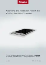
background image

To avoid the risk of accidents or damage to the appliance it is 

essential

to read these instructions before it is installed and used for the first time.

en-GB

M.-Nr. 09 055 450

Operating and installation instructions
Ceramic hobs with induction

Summary of Contents for CS 1212-1

Page 1: ... accidents or damage to the appliance it is essential to read these instructions before it is installed and used for the first time en GB M Nr 09 055 450 Operating and installation instructions Ceramic hobs with induction ...

Page 2: ...rst time 19 Switching on the hob for the first time 19 Induction 20 The induction principle 20 Noises 21 Pans 22 Tips on saving energy 23 Settings 24 Operation 25 Cooking zone controls 25 Switching on 25 Switching off 25 Residual heat indicator 25 Auto heat up 26 Booster 27 Keeping warm 29 Safety features 30 System lock 30 Safety switch off 30 Overheating protection 31 Cleaning and care 32 Ceramic...

Page 3: ...ion 38 Safety distances 39 Installation notes 43 Building in dimensions 44 CS 1212 1 44 CS 1221 1 CS 1222 45 Installing several ProLine elements 46 Installation 48 Electrical connection 52 After sales service 54 Contact in case of malfunction 54 Data plate 54 Warranty 54 Product data sheets 55 ...

Page 4: ...amage to the hob please read these instructions carefully before installation and before using it for the first time They contain important notes on installation safety use and maintenance Miele cannot be held liable for damage caused by non compliance with these instructions Keep these instructions in a safe place and ensure that new users are familiar with the content Pass them on to any future ...

Page 5: ... supported by the manufacturer and could be dangerous This hob is not intended for use by people with reduced physical sensory or mental capabilities or lack of experience and knowledge unless they have been given supervision and instruction concerning its use by a person responsible for their safety They may only use the hob unsupervised if they have been shown how to use it in a safe way They mu...

Page 6: ...t for a while after be ing switched off Keep children well away from the hob until it has cooled down and there is no danger of burning Danger of burning Do not store anything which might arouse a child s interest in storage areas above or behind the hob Otherwise they could be tempted into climbing onto the appliance with the risk of burning themselves Risk of burning and scalding Place pots and ...

Page 7: ...ified electrician To avoid the risk of damage to the hob make sure that the con nection data on the data plate voltage and frequency match the mains electricity supply before connecting it to the mains Consult a qualified electrician if in doubt Do not connect the hob to the mains electrical supply by a multi socket adapter or extension lead These are a fire hazard and do not guarantee the require...

Page 8: ...epair work Ensure that power is not supplied to the appliance until after it has been installed or un til any maintenance or repair work has been carried out Danger of electric shock Do not use the hob if it is faulty or if the ceramic surface is cracked chipped or damaged in any way Switch it off immediately Disconnect the hob from the mains electricity sup ply Contact Miele Service If the hob is...

Page 9: ... such items or substances in a drawer under the hob Cutlery inserts must be heat resistant Do not heat an empty pan Do not heat up food in closed containers e g tins or sealed jars on the hob as pressure can build up in the container causing it to explode Do not cover the hob e g with a hob cover a cloth or protective foil The material could catch fire shatter or melt if the hob is switched on by ...

Page 10: ...tances Do not drop anything on the ceramic surface Do not place hot pans on the display as this could cause damage to the electronics underneath Do not place hot pans on the area around the display Do not allow solid or liquid sugar or pieces of plastic or aluminium foil to get onto the hob when it is hot as they can damage the ceramic surface when it cools down If this should occur switch off the...

Page 11: ...Metal utensils stored in a drawer under the hob can become hot if the appliance is used intensively for a long time The hob is fitted with a cooling fan If a drawer is fitted directly un derneath the hob ensure that there is sufficient space between the drawer and its contents and the underside of the hob in order to en sure sufficient ventilation for the hob If a drawer is fitted directly underne...

Page 12: ...ean this hob The steam could reach electrical components and cause a short cir cuit If the hob is built in over a pyrolytic oven the hob should not be used whilst the pyrolytic process is being carried out as this could trigger the overheating protection mechanism on the hob see relev ant section ...

Page 13: ...terials They also contain specific materials com pounds and components which were essential for their correct function and safety These could be hazardous to hu man health and to the environment if disposed of with your domestic waste or if handled incorrectly Please do not therefore dispose of your old appliance with your household waste Please dispose of it at your local com munity waste collect...

Page 14: ...pliance 14 Hob CS 1212 1 a Cooking zone with TwinBooster b Cooking zone with Booster c Cooking zone display d Cooking zone symbols e Indicators f Control for the rear cooking zone g Control for the front cooking zone ...

Page 15: ...Guide to the appliance 15 CS 1221 1 a Cooking zone with TwinBooster b Cooking zone display c Indicators d Cooking zone controls ...

Page 16: ... TwinBooster b Cooking zone with Booster c Cooking zone display d Cooking zone symbols e Indicators g Control for the front cooking zone h Control for the rear cooking zone Indicators B l In operation indicator m Booster indicator n Residual heat indicator ...

Page 17: ...ooster level 1 activated TwinBooster level 2 activated The system lock has been activated Safety switch off see Safety features Overheating protection see Safety features Cooking zones Cooking zone CS 1212 1 Ø in cm Rating in watts for 230 V 10 16 Normal Booster 1400 2200 16 23 Normal TwinBooster level 1 TwinBooster level 2 2300 3000 3700 Total 3700 Pans with a base diameter within the given range...

Page 18: ... depending on the size and material of the pans used Cooking zone CS 1222 Ø in cm Rating in watts for 230 V 10 16 Normal Booster 1400 2200 14 20 Normal TwinBooster level 1 TwinBooster level 2 1850 2500 3000 20 x 30 Normal TwinBooster level 1 TwinBooster level 2 2300 3000 3700 Total 3700 Pans with a base diameter within the given range may be used The wattage quoted may vary depending on the size a...

Page 19: ...power sup ply all of the indicators in the display will light up for approx 1 second for testing As soon as they go out the hob is ready for use The metal components have a protect ive coating which may give off a slight smell when heated up for the first time The induction coils may also give off a slight smell for the first few hours of op eration This smell will be less notice able with each su...

Page 20: ...f the pan is unsuitable non magnetic base if the diameter of the base of the pan is too small if the pan is taken off the cooking zone when it is switched on If a suitable pan is placed on the cook ing zone within 3 minutes the will go out and you can continue as normal If no pan or an unsuitable pan is placed on the cooking zone the cooking zone will switch off automatically after 3 minutes and w...

Page 21: ...rials e g in a sandwiched base it might emit a crackling sound Whistling might occur if linked zones see Operation Booster are being used at the same time and the pans also have bases made of layers of dif ferent materials You might hear a clicking sound from the electronic switches especially on lower settings A whirring sound when the cooling fan comes on This switches on to protect the electron...

Page 22: ... dis play The composition of the pan base can affect the evenness of the cooking res ults e g when making pancakes To make optimum use of the cooking zones choose a pan with a suitable base diameter see Guide to the ap pliance Cooking zones If the pan is too small it will not be recognised and the symbol will appear in the cooking zone display Only use pots and pans with smooth bases Rough bases w...

Page 23: ...when cooking small quantities A smaller pan uses less energy than a larger pan with very little in it Cook with as little water as possible Once food has come to the boil or the oil in the pan is hot enough for frying reduce the heat to a lower set ting Use a pressure cooker to reduce cooking times ...

Page 24: ...s of food to the boil e g casseroles Thickening custard and sauces e g hollandaise 6 7 Gently frying meat fish and sausages without overheating the fat 6 7 Frying pancakes potato fritters etc 7 Braising meat 8 Boiling large quantities of water Bringing to the boil 9 These settings should only be taken as a guide The power of the induction coils will vary depending on the size and material of the p...

Page 25: ...up The residual heat indicator will light up after a certain temperature has been reached Switching off Turn the cooking zone control anti clockwise to 0 When all cooking zones are switched off the in operation indicator will go out Residual heat indicator If a cooking zone is hot the residual heat indicator will light up when it has been switched off The residual heat in dicator will only go out ...

Page 26: ...e continued cooking setting you want The continued cooking level must be set within 5 seconds of activating Auto heat up You can change the continued cook ing level up to approx 10 seconds after activating Auto heat up If you hold down the cooking zone control for too long the system lock will be activated and will appear in the cooking zone display lights up in the cooking zone display during the...

Page 27: ...ng zones at the same time Hobs with 4 cooking zones the booster function can only be used on a max imum of two cooking zones at the same time Cooking zones are linked in pairs to supply the power for the booster func tion When the booster function is selected a proportion of energy is taken away from the linked cooking zone and the following happens within the pairs Auto heat up is deactivated the...

Page 28: ... will appear in the cooking zone dis play the B Booster indicator will light up To switch on the TwinBooster level 2 Turn the cooking zone control clock wise past 9 to B I II and back again to 9 will appear in the cooking zone dis play the B Booster indicator will light up Turn the cooking zone control once more clockwise past 9 to B I II and back again to 9 will appear in the cooking zone dis pla...

Page 29: ...ours Only use pans for keeping food warm Cover the pan with a lid Stir firm or viscous food mashed potatoes stew occasionally Nutrients are lost when food is cooked and continue to diminish when food is kept warm The longer food is kept warm the greater the loss of nutrients Try to ensure that food is kept warm for as short a time as possible Setting the keeping warm function Turn the control cloc...

Page 30: ...he point of resistance and hold it until appears in the display Deactivating Turn the outer right cooking zone control anti clockwise to the point of resistance and hold it until goes out in the display Safety switch off The safety switch off mechanism is triggered automatically if one of the cooking zones is heated for an unusu ally long period of time This period of time depends on the power lev...

Page 31: ... in the cook ing zone display Further cooking zones switch off automatically Switch off the affected cooking zone If the cooking zone is not switched off and will flash alternately in the cooking zone display You can use the cooking zones again as usual when the fault code has gone out The overheating protection mechanism can be triggered by heating up an empty pan fat or oil being heated on a hig...

Page 32: ...ges or cleaning agents Allow the ProLine element to cool down before cleaning Clean the ProLine element and ac cessories after each use Dry the ProLine element thoroughly after cleaning it with water to avoid limescale residue Unsuitable cleaning agents To avoid damaging the surfaces of the appliance do not use washing up liquid cleaning agents containing soda al kalines ammonia acids or chlorides...

Page 33: ... cloth Do not apply the cleaner while the hob is still hot as this can result in marking Please follow the cleaning agent manufacturer s instructions Finally wipe the glass ceramic surface with a damp cloth and polish with a soft dry cloth Residues can burn onto the hob the next time it is used and cause damage to the glass ceramic surface Ensure that all cleaning agent residues are re moved Spots...

Page 34: ... help prevent resoiling see Optional accessories Do not use ceramic and stainless steel cleaner or stainless steel condi tioning agent on the printing This would rub the printing off These areas should be only cleaned with a solution of warm water and a little washing up liquid applied with a soft sponge Rotary controls Clean the rotary control s using a solution of warm water and a little washing...

Page 35: ...till not turn on after resetting the trip switch in the fuse box or the residual cur rent current device contact a qualified electrician or Miele Service A smell and vapours are given off when the new appliance is being used The metal components have a protective coating When the appliance is used for the first time this causes a smell and possibly also vapour The material from which the induction...

Page 36: ...I has been activated on the linked cooking zone appears in the cook ing zone display The overheating protection mechanism has been ac tivated See Overheating protection appears in the display for several seconds after a cooking zone has been switched on The system lock has been activated You need to deactivate the system lock see Sys tem lock appears in the display for several seconds after a cook...

Page 37: ... appliances These products can be ordered through the Miele Webshop They can also be ordered from Miele see end of this booklet for contact de tails or from your Miele dealer Ceramic and stainless steel hob cleaner 250 ml Removes heavy soiling limescale de posits and aluminium residues Microfibre cloth Removes finger marks and light soiling ...

Page 38: ...its must be treated with 100 C heat resistant adhesive which will not dissolve or distort Any backmoulds must be of heat resistant material The ProLine element must not be installed over a fridge fridge freezer freezer dishwasher washing machine washer dryer or tumble dryer This CombiSet must not be installed above an oven unless it has a built in cooling fan After installation the mains connectio...

Page 39: ...d above it If the cooker hood manufacturer s in structions are not available or if com bustible objects are installed above the ProLine element e g cabinets utensil rail etc a minimum safety distance of at least 760 mm must be maintained When two or more ProLine elements which have different safety distances are installed together below a cooker hood you should observe the greatest safety distance...

Page 40: ...e rear edge of the worktop 50 mm Minimum distance between the worktop cut out and a tall unit or wall to the right or left of it 40 mm CS 1212 CS 1212 1 CS 1221 CS 1221 1 CS 1234 CS 1234 1 CS 1223 CS 1222 50 mm CS 1112 CS 1122 CS 1134 CS 1326 CS 1327 CS 1411 100 mm CS 1012 CS 1012 1 CS 1012 2 150 mm CS 1421 CS 1312 CS 1322 200 mm CS 1034 CS 1034 1 250 mm CS 1011 CS 1011 1 CS 1021 CS 1021 1 CS 1018...

Page 41: ... minimum gap between the under side of the hob and the top of an oven is 15 mm the top of an interim shelf is 15 mm the base of a drawer is 75 mm Interim shelf It is not necessary to fit an interim shelf underneath the hob but one may be fit ted if you wish Leave a gap of 10 mm at the back of the shelf to accommodate the cable We recommend a gap at the front of the shelf of 20 mm to ensure good ve...

Page 42: ...t be maintained between the cut out and the cladding If the niche cladding is made from a non combustible material e g metal natural stone ceramic tiles the minimum safety distance between the cut out and the cladding will be 50 mm less the thickness of the cladding Example 15 mm niche cladding 50 mm 15 mm minimum safety distance of 35 mm a Masonry b Niche cladding dimension x thickness of the nic...

Page 43: ...ne element and the worktop The sealing strip under the edge of the top part of the appliance provides a sufficient seal for the worktop Tiled worktop Grout lines and the hatched area un derneath the ProLine element frame must be smooth and even If they are not the ProLine element will not sit flush with the worktop and the sealing strip underneath the top part of the ap pliance will not provide a ...

Page 44: ...Building in dimensions I N S T A L L A T I O N 44 CS 1212 1 a Spring clamps b Front c Casing depth d Casing depth including mains connection box with mains connection cable L 2000 mm ...

Page 45: ...Building in dimensions I N S T A L L A T I O N 45 CS 1221 1 CS 1222 a Spring clamps b Front c Casing depth d Casing depth including mains connection box with mains connection cable L 2000 mm ...

Page 46: ...e elements 46 Example 3 ProLine elements a Spring clamps b Spacer bars c Gap between spacer bars and worktop d Cover e ProLine element width less 8 mm f ProLine element width g ProLine element width less 8 mm h Worktop cut out ...

Page 47: ...roLine elements are 288 mm 380 mm or 576 mm wide depending on model see Building in dimensions Spacer bars When installing several ProLine elements an additional spacer bar must be fitted in between the individual ProLine elements The position for securing the spacer bar will depend on the width of the ProLine element Installation with a downdraft extractor Please refer to the separate Downdraft e...

Page 48: ... Seal any cut surfaces on the wood worktops with a special varnish silic one rubber or resin to prevent the wood from swelling as a result of moisture The sealant must be heat resistant Make sure that the sealant does not come into contact with the top of the worktop Position the spring clamps and the spacer bars at the top edge of the cut out in the positions shown in the illustrations Secure the...

Page 49: ...d spacer bars Stick the tape to the top edge of the cut out in the positions shown in the diagram Position the spring clamps and spacer bars on the top edge of the cut out and press them firmly into place Apply silicone to the side and lower edges of the spring clamps and the spacer bars Then fill gap between spacer bar and the worktop with silicone ...

Page 50: ...element until it clicks into position When do ing this make sure that the seal of the appliance sits flush with the worktop on all sides This is important to en sure an effective seal all round Do not use any additional sealant e g silicone on the ProLine ele ment If the seal does not meet the worktop correctly on the corners the corner ra dius R4 can be carefully scribed to suit Installing severa...

Page 51: ...ains electricity supply Check that each ProLine element is working Removing a ProLine element If the ProLine element cannot be ac cessed from below you will need a special tool to remove it If the ProLine element can be ac cessed from below push it upwards to remove it Push the back of the ap pliance out first ...

Page 52: ... of or inadequacy of an on site earthing system e g electric shock This ProLine element must be con nected to the electrical supply by a qualified electrician The electrician must be familiar with and comply with the national regula tions and any additional regulations of the local electricity provider e g BS 7671 in the UK After installation ensure that all elec trical components are shielded and...

Page 53: ... the middle black button springs out Built in circuit breakers Circuit breakers at least type B or C Switch the lever from 1 on to 0 off Residual current device RCD Switch the main switch from 1 on to 0 off or press the test button Replacing the power cable Risk of electric shock from mains voltage Incorrect connection to the power supply may result in an electric shock The power cable must only b...

Page 54: ...d as described in this booklet Please quote the model and serial number of your appliance when contacting Miele This information can be found on the data plate Data plate Stick the extra data plate supplied with the appliance here Make sure that the model number matches the one specified on the back cover of this document Warranty For information on the appliance warranty specific to your country ...

Page 55: ...ption per cooking zone or area cal culated per kg ECelectric cooking 1 185 2 Wh kg 2 168 9 Wh kg Energy consumption for the hob calculated per kg ECelectric hob 177 1 Wh kg Information for domestic electric hobs In acc with regulation EU No 66 2014 MIELE Model name identifier CS 1221 1 Number of cooking zones and or areas 1 For circular cooking zones diameter of useful sur face area cooking zone F...

Page 56: ... zones diameter of useful sur face area cooking zone For non circular cooking zones or areas length and width of useful surface area per electric cook ing zone or area 1 Ø 100 160 mm 2 Ø 200 200x300 mm 3 4 5 6 Energy consumption per cooking zone or area cal culated per kg ECelectric cooking 1 185 2 Wh kg 2 188 7 Wh kg Energy consumption for the hob calculated per kg ECelectric hob 187 0 Wh kg ...

Page 57: ......

Page 58: ......

Page 59: ... Sapura Kencana Petroleum Solaris Dutamas No 1 Jalan Dutamas 1 50480 Kuala Lumpur Malaysia Phone 603 6209 0288 Fax 603 6205 3768 Miele New Zealand Limited IRD 98 463 631 Level 2 10 College Hill Freemans Bay Auckland 1011 New Zealand Tel 0800 464 353 Internet www miele co nz New Zealand Miele Pte Ltd 163 Penang Road 04 03 Winsland House II Singapore 238463 Tel 65 6735 1191 Fax 65 6735 1161 E Mail i...

Page 60: ...M Nr 09 055 450 07 en GB ...

Reviews: