background image

Operating and Installation
Instructions

Ventilation System
DA 239-3

To prevent accidents
and machine damage,
read these instructions

before

installation or use.

UV

M.-Nr. 05 853 540

Summary of Contents for DA 239-3

Page 1: ...Operating and Installation Instructions Ventilation System DA 239 3 To prevent accidents and machine damage read these instructions before installation or use UV M Nr 05 853 540 ...

Page 2: ...2 ...

Page 3: ...ase filter timer 13 Reprogramming the grease filter timer 14 Cleaning and Care Cleaning the casing 15 Grease filters 16 Changing the light bulb 17 After Sales Service Installation instructions Caring for the environment Installation accessories Plywood backing Electrical data Appliance dimensions Installation Attaching the hood and motor assembly to the wall 28 Inserting the non return flap 29 Att...

Page 4: ...ctrical safety of this appliance continuity must exist between the appliance and an effective grounding system It is imperative that this basic safety requirement be met If there is any doubt have the electrical system of the house checked by a qualified electrician The manufacturer can not be held responsible for damages caused by the lack or inadequacy of an effective grounding system Before con...

Page 5: ...not allow children to play with or operate the appliance or its controls Supervise its use by the elderly or infirm Be careful when preparing a flambé beneath the hood Flames may be drawn up into the hood by the suction or grease filters may catch fire Never operate gas burners without pots Do not leave cooking surfaces unattended while in use Overheated food oil and grease can catch fire Do not u...

Page 6: ...OF INJURY TO PERSONS IN THE EVENT OF A RANGE TOP GREASE FIRE OBSERVE THE FOLLOWING SMOTHER FLAMES with a close fitting lid cookie sheet or metal tray then turn off the burner BE CAREFUL TO PREVENT BURNS If the flames do not go out immediately EVACUATE AND CALL THE FIRE DEPARTMENT NEVER PICK UP A FLAMING PAN You may be burned DO NOT USE WATER including wet dishcloths or towels a violent steam explo...

Page 7: ...ion cords do not guarantee the required safety of the appliance e g danger of overheating Do not install this hood over cooktops burning solid fuel Any fittings sealant or materials used to install the ductwork must be made of approved non flammable materials Never connect an exhaust hood to an active chimney dryer vent vent flue or room ventilating ductwork Seek professional advice before connect...

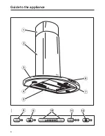
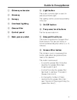
Page 8: ...Guide to the appliance 8 ...

Page 9: ...ayed Shut Down feature The fan can be set to turn off automatically after either 5 or 15 minutes l Grease filter button The indicator next to the grease filter button lights when the grease filters need to be cleaned This button is also used to reset the grease filter timer after cleaning the grease filters see Cleaning and Care to show how long the grease filter has been in use see Operation Grea...

Page 10: ...hood comes equipped with a non return flap This flap automatically closes when the hood is turned off so that no exchange of outside air and room air can occur When the hood is turned on the air pressure of the exhaust fan automatically opens the flap blowing the inside air and cooking odors outside Functional description 10 ...

Page 11: ...ng Intensive setting Level 4 yellow indicator should be used for a short period when frying or cooking food with a strong aroma Fan performance The maximum air flow capacity is 625 cfm Factors such as narrow duct diameter and bends will affect this value Level 1 operates at 40 capacity Level 2 operates at 60 capacity Level 3 operates at 80 capacity Level 4 operates at 100 capacity Delayed Shut Dow...

Page 12: ...light button briefly to turn on the lighting The light button indicator illuminates Press the light button briefly again to turn off the lighting The light button indicator will go out Dimming the lighting The brightness of the lighting can be adjusted While the lighting is turned on press the light button The lighting will dim until the button is released If the button is pressed again the lighti...

Page 13: ...e filter button for about 3 seconds The indicator will go out Checking the grease filter timer To check the percentage of time already used Press the On Off button to turn the fan on Press the grease filter button The number of flashing _ indicators show the percentage of programmed hours that have been used 1 indicator less than 25 2 indicators less than 50 3 indicators less than 75 4 indicators ...

Page 14: ... more difficult Press the On Off button to turn off the fan Press the Delayed Shut Down and grease filter buttons at the same time The indicator for the grease filter and one of the _ indicators will flash The lit _ indicator shows the programmed time 1st indicator from the left 20 hours 2nd indicator from the left 30 hours 3rd indicator from the left 40 hours 4th indicator from the left 50 hours ...

Page 15: ...into the electronics and cause damage Glass surfaces can be cleaned using glass cleaner Avoid cleaning agents containing soda acids or chlorides abrasive cleaning agents e g powder or cream cleansers abrasive sponges e g pot scourers or sponges which have been previously used with abrasive cleaning agents These will damage the surface Stainless steel Stainless steel surfaces can be cleaned using a...

Page 16: ...rmanent discoloration of the filter surface Performance of the filter will not be affected by this discoloration After cleaning the filters can be placed on a towel to air dry While the filters are removed clean any dirt or grease from the filter casing to prevent the risk of fire When putting the grease filters back make sure that the locking clips are visible facing down towards the cooking surf...

Page 17: ...own Do not touch the bulb surface Fingerprints or body oils deposited on the bulb will decrease the life of the bulb Please follow the bulb manufacturer s instructions To change a bulb Remove the outer ring a Support the glass c while detaching the circlip b Be careful not to let the glass fall out Pull the old bulb d out of its socket and replace it with a new one Reinstall the glass circlip and ...

Page 18: ...al Service Department USA 1 800 999 1360 techserv mieleusa com CDN 1 800 565 6435 service miele ca When contacting the Technical Service Department please quote the model and serial number of your appliance These are shown on the data plate which is visible when the grease filter is removed After Sales Service 18 ...

Page 19: ...Installation Instructions ...

Page 20: ...20 ...

Page 21: ...ren ensure that any plastic wrappings bags etc are disposed of safely and kept out of their reach Disposal of an old appliance Old appliances may contain materials that can be recycled Please contact your local recycling authority about the possibility of recycling these materials Before discarding an old hood unplug it from the outlet and cut off its power cord to prevent hazards Caring for the e...

Page 22: ...Installation accessories 22 ...

Page 23: ... Upper retaining plate secures the chimney extension f Lower retaining plate g Locking plate secures the canopy 8 screws 5 x 40 mm for supporting the motor assembly and canopy S8 wall anchors included in packaging are not for use in USA CDN 6 Screws 3 9 x 7 5 mm for securing the chimney and chimney extension CAUTION During the installation process please be careful of sharp edges that can cause ha...

Page 24: ...location of the motor assembly as outlined in Attaching the hood and motor assembly to the wall Mark a horizontal line 3 76 mm above and 9 229 mm below the mounting screw locations Find the studs to the left and right of the mounting location by tapping the wall or using a stud finder Mark the center of each of the studs with a vertical line Be careful not to damage any wiring or plumbing that may...

Page 25: ...d on the data plate located behind the grease filters match the household electrical supply before installing the hood If there is any question concerning the electrical connection of this appliance to your power supply please consult a licensed electrician or call Miele s Technical Service Department USA 1 800 999 1360 CDN 1 800 565 6435 WARNING THIS APPLIANCE MUST BE GROUNDED Important The hood ...

Page 26: ...nd the ceiling must be at least 7 8 20 mm Cut out area in wall or ceiling for entrance of 6 150 mm ductwork with reducing collar 5 125 mm Metric Conversion table mm Inch 25 1 95 3 3 4 110 4 5 16 250 9 13 16 270 10 5 8 308 12 1 8 350 13 3 4 500 19 11 16 510 20 1 16 805 31 11 16 850 33 7 16 Appliance dimensions 26 ...

Page 27: ...e Warning and Safety instructions for further information 26 65 cm is recommended for all installations to allow for optimum work space under the hood Installation procedures differ depending on hood model and venting method Determine the minimum safety distance S before beginning the installation When marking the wall make sure that S is maintained and that measurement H does not extend into this...

Page 28: ...ere the hood will be installed Mark the location of the 2 motor assembly support screws S 10 1 4 260 mm above the cooktop and 4 15 16 125 mm to the right and left of the centerline Layout the location of the lower retaining plate screw directly on the centerline S 19 1 2 495 mm above the cooktop Hold the upper retaining plate flush against the ceiling so that the centerline passes through the notc...

Page 29: ...screw heads to protrude about 1 4 5 mm so the motor can hang on them Inserting the non return flap Place the non return flap into the exhaust connection at the top of the motor assembly so that the flaps open in the up direction Turn the non return flap slightly to lock it in place The hood is designed for use with 6 150 mm ductwork If 5 125 mm ductwork is to be used a reducing collar must be inst...

Page 30: ...er the 2 mounting screws in the wall Making sure the assembly is level drill through the 2 remaining holes on the edge of the mounting bracket using a 1 8 3 mm diameter bit Secure the assembly to the wall using the top 2 screws only Installation 30 ...

Page 31: ...re the canopy by guiding the 2 remaining screws through the locking plate and the holes in the motor assembly see illustration Tighten the screws Connecting the exhaust duct Connect the ductwork to the exhaust connection using appropriate measures for the type of ductwork being installed hose clamp duct tape etc Direct the duct through the back wall or the ceiling Installation 31 ...

Page 32: ...sembly Insert the 6 prong connector into the receptacle right of the motor assembly Secure the cords with the ties as shown above Plug in the power cord Installing the chimney extension The chimney extension allows the hood to be installed at various distances from the ceiling Carefully ease apart the sides of the chimney extension and hook it behind the upper retaining plate Be careful of sharp e...

Page 33: ...stration Carefully ease apart the sides of the chimney and slide it over the extension Hook it behind the extension and both retaining plates Hold it high enough to clear the top of the canopy to avoid scratches Slide the chimney down so that it sits at least 3 8 1 cm inside the canopy and adjust it as necessary Pull off the protective shields If the chimney is not tall enough an optional chimney ...

Page 34: ...by tightening the screw located on its interior Turn the screw clockwise to raise the canopy and counter clockwise to lower it Tighten as much as necessary to level the front of the canopy Return the grease filters Before using the appliance remove the grease filter and remove the protective foil from the filter frame Return the filter Installation 34 ...

Page 35: ...ng should be as short and straight as possible and the number of sharp bends should be minimized For most efficient air extraction the diameter of the ductwork should not be less than 6 150 mm Use of flat ducts also reduces the air extraction efficiency Noise levels of the hood will increase if flat ducts or round ducts of less than 6 150 mm in diameter are used Use smooth or flexible pipes made f...

Page 36: ...od vent to an existing inactive chimney or vent flue Condensate trap Important If the ductwork runs through rooms ceilings garages etc where temperature variations exist it may need to be insulated to reduce condensation In some cases a condensate trap may also be required to collect and evaporate any condensate which may occur When installing a condensate trap ensure that it is positioned vertica...

Page 37: ...37 ...

Page 38: ...38 ...

Page 39: ...39 ...

Page 40: ...M Nr 05 853 540 01 Alteration rights reserved 4103 This paper was bleached without the use of chlorine ...

Reviews: