background image


TECHNICAL INFORMATION 

DGC 6xxx Combi-Steam Ovens  


© 

2018 Miele USA 


Summary of Contents for DGC 6 Series

Page 1: ...TECHNICAL INFORMATION DGC 6xxx Combi Steam Ovens 2018 Miele USA ...

Page 2: ... 4 5 Door Contact Switch S24 Removal 20 4 6 Cable Duct Removal 20 4 7 Hinge Replacement 22 020 Door 23 4 Service 24 4 1 Door Removal 24 4 2 Door Disassembly 24 4 3 Door Handle Removal 26 4 4 Door Assembly 26 4 5 Door Installation 26 030 Cavity 27 1 Technical Data 28 2 Function 28 2 1 Heat Flow Temperature Sensor 2R30 10 28 3 Fault Repair 28 3 1 Cavity Surface Scratched 28 3 2 Noisy Operation 29 3 ...

Page 3: ... Air Humidity 47 2 5 5 Heat Flow Sensor WFS 48 3 Fault Repair 48 3 1 Knocking Noises 48 3 2 Residual Water in Cavity 49 3 3 Hose Kinked 49 3 4 Condensate Drain Hose Cannot Be Connected 50 4 Service 51 4 1 Air Flap Motor M28 Removal 51 4 2 Cavity Temperature Sensor 1R30 10 Removal 51 4 3 Drain Pump M8 Removal 52 4 4 Steam Generator R25 Removal 52 4 5 Convection Fan M2 2 Removal 54 4 6 Pinch Drain V...

Page 4: ... 3 Combi Cooking 71 2 5 4 Combination Cooking with Convection Plus 71 2 5 5 Combination Cooking with Browning Bake 71 2 5 6 Combination Cooking with Broil 72 2 6 Care Programs 72 2 6 1 Rinsing 72 2 6 2 Soak 72 2 6 3 Drying 72 2 6 4 Descaling 73 2 6 4 1 Descaling 73 2 6 4 2 Descaling Cycle 73 2 7 Machine Response after a Power Failure 73 2 8 Wireless Roast Probe 73 2 8 1 Components 73 2 8 2 Descrip...

Page 5: ...nic Interface Fault 100 3 8 Fault Code F54 Roast Probe Short Circuited 100 3 9 Fault Code F55 Safety Cut Out 100 3 10 Fault Code F60 Power Electronic Temperature Limit Exceeded 101 3 11 Fault Code F74 Drain Valve Fault 101 3 12 Fault Code F94 Plumbed Water Connection Water Intake Fault 101 3 13 Fault Code F190 Plumbed Water Connection Valve Defective 101 3 14 Fault Code F191 Heat Flow Pt1000 Tempe...

Page 6: ...ure 010 1 Removing the Appliance from a Housing Unit 16 Figure 010 2 Lid Removal 17 Figure 010 3 Right Side Panel Removal 18 Figure 010 4 Rear Left Side Panel Removal 19 Figure 010 5 Spacer Bar on Rear Panel 20 Figure 010 6 Door Switch Removal 20 Figure 010 7 Cable Duct Screws 21 Figure 010 8 Hinge Screws Left Side Shown 22 Figure 020 1 Hinge Brackets 24 Figure 020 2 Door Removal 24 Figure 020 3 C...

Page 7: ...g the Steam Generator at at Slight Angle 54 Figure 035 11 Inner Rear Panel Screws 55 Figure 035 12 Convection Fan Screws 55 Figure 035 13 Drain Valve Removal 56 Figure 035 14 Terminal Block 57 Figure 040 1 Leaf Springs on Telescopic Rails 64 Figure 040 2 Lift Motor Screws 65 Figure 040 3 Cog Wheel Setting 66 Figure 040 4 Water Container Removal 66 Figure 040 5 Water Container Spring 67 Figure 045 ...

Page 8: ... Information 10 Table 030 1 Heater Element Data 28 Table 030 2 Oven Light Data 28 Table 030 3 Heat Flow Temperature Sensor Resistance Chart 28 Table 035 1 Air Flap Motor Data 44 Table 035 2 Cavity Temperature Sensor Data 44 Table 035 3 Steam Generator Heater Data 44 Table 035 4 Steam Generator Temperature Regulator Data 44 Table 035 5 Convection Fan Data 44 Table 035 6 Drain Pump Data 44 Table 040...

Page 9: ...e protection mat no 5057680 to prevent cuts by sharp edges B Modification History When Who What 3 7 2018 Jessica Naples Tech service bulletin added 7 11 2017 Jessica Naples Minor changes throughout 10 19 2016 Jessica Naples Tech service bulletin added 3 22 2016 Jessica Naples Compilation for Website C Technical Data Model number DGC 6500 6600 DGC 6700 6800 DGC 6705 6805 Oven type Single Single Sin...

Page 10: ...700W Frequency 60Hz 60Hz 60Hz Fuse 20A 20A 20A Controls SensorTronic MTouch MTouch Table C 1 Appliance Information 1 When installing the appliance in a cabinet make sure that the cabinet and the wall can support the weight of the appliance D Layout of Electrical Components 1 Optical Interface Figure D 1 Optical Interface for Diagnostic Support and Program Updating ...

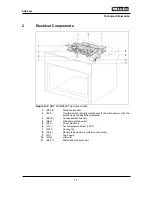
Page 11: ...tually located next to the drain pump not by the electronic as the illustration indicates 3 B3 19 Condensate tank sensor 4 S60 Lift panel position switch 5 N1 1 Power electronic 6 1F1 Fan temperature limiter 158 F 7 M2 1 Cooling fan 8 N1 6 Roast probe electronic with wire connection 9 M7 Feed pump 10 M19 Lift motor 11 B3 17 Water tank present sensor ...

Page 12: ...r 10 2F1 5 Steam generator temperature monitor 11 R15 Broil element 12 2M2 1 Heat flow fan 13 2R30 10 Heat flow temperature sensor Pt1000 14 1R30 10 Oven Pt1000 temperature sensor 15 R30 34 Cool air Pt1000 temperature sensor 16 R13 Top heater element 17 X3 1 Terminal block 18 Z2 Interference suppression capacitor 19 3F1 Convection temperature limiter 20 M2 2 Convection fan 21 M28 Air flap motor 22...

Page 13: ...low switch 3 B3 19 Condensate tank sensor 4 N1 10 Lighting electronic 5 S60 Lift panel position switch 6 N1 1 Power electronic 7 1F1 Fan temperature limiter 158 F 8 1M2 1 Cooling fan 9 1Y63 2Y63 Inlet valves DGC 6x05 only 10 N1 6 Roast probe electronic 11 M7 Feed pump 12 M19 Lift motor 13 B3 17 Fill level sensor ...

Page 14: ...erature limiter 10 2F1 5 Steam generator temperature limiter 11 W17 Roast probe antenna 12 2M2 1 Heat flow fan 13 2R30 10 Heat flow temperature sensor Pt 1000 14 1R30 10 Oven cavity temperature sensor Pt 1000 15 R15 Broil element 16 R13 Top heater element 17 X3 1 Terminal block 18 Z2 Interference suppression capacitor 19 3F1 Convection temperature limiter 20 M2 2 Convection fan 21 M28 Air flap 22 ...

Page 15: ...Technical Information 15 DGC 6xxx 010 Casing ...

Page 16: ... 3 Fault Repair 3 1 CleanSteel Surface Scratched Cause A cleaner unsuitable for use with CleanSteel was used Remedy Do not clean the cavity with abrasive cleaning agents see the operating instructions 4 Service 4 1 Removal from a Housing Unit 1 Remove all accessories from the cavity 2 Remove the retaining screws see Figure 010 1 Item 1 3 Remove the appliance 4 Disconnect the power connection Figur...

Page 17: ...ining nuts 5 5mm from the underside of the lid next to the water and condensate tanks 6 Remove the eight T20 screws see Figure 010 2 Item 1 7 Remove the lid Figure 010 2 Lid Removal 4 3 Right Side Panel Removal 1 Remove the appliance from its housing unit see Section 010 4 1 2 Disconnect the appliance from the power supply 3 Remove the lid see Section 010 4 2 4 Remove the retaining screws see Figu...

Page 18: ... with the rear panel 1 Remove the appliance from its housing unit see Section 010 4 1 2 Disconnect the appliance from the power supply 3 Remove the lid see Section 010 4 2 4 Remove the five T20 screws securing the left side panel as well as the four T20 screws securing the rear panel see Figure 010 4 Item 1 5 Remove the rear left side panel ...

Page 19: ...ide Panel Removal Note Some models have a spacer bar attached to the rear panel see Figure 010 5 For these models remove the two T20 screws securing the spacer bar take the spacer bar off and then remove the two T20 screws securing the bottom of the rear panel ...

Page 20: ... power supply 4 Remove the lid see Section 010 4 2 5 Remove the rear left side panel refer to Section 010 4 4 6 Remove the two T20 screws securing the hinge on the left side 7 Disconnect the switch connections 8 Lift the hinge up 9 Unclip the switch assembly at the bottom Figure 010 6 Item 1 and slide it out of the hinge assembly Figure 010 6 Door Switch Removal 4 6 Cable Duct Removal 1 Remove the...

Page 21: ...r left side panel refer to Section 010 4 4 5 Pull off the black heat flow fan hose from the cable duct 6 Remove the T20 screw securing the interference suppression capacitor to the cable duct See Figure 010 7 Item 1 7 Remove the T20 screw securing the cable duct to the appliance See Figure 010 7 Item 2 Figure 010 7 Cable Duct Screws 1 2 ...

Page 22: ...ng each hinge see Figure 010 8 Item 1 and remove the hinges from the appliance Figure 010 8 Hinge Screws Left Side Shown 5 Align the rear hinge screw opening with the base plate and insert one flat T20 screw to keep the hinge aligned Leave the screw loose for later adjustment 6 Support the base plate with a block of wood 7 Open the door this aligns the base plate with the hinge 8 Raise the fascia ...

Page 23: ...Technical Information 23 DGC 6xxx 020 Door ...

Page 24: ...020 1 Figure 020 1 Hinge Brackets 3 Close the door to the point where resistance is felt when it is almost closed 4 Remove the door upwards see Figure 020 2 Figure 020 2 Door Removal 4 2 Door Disassembly 1 Remove the door see Section 020 4 1 2 Remove the two T20 screws securing the plastic corner bracket on each side see Figure 020 3 Item 1 ...

Page 25: ... the holding strip with seal see Figure 020 4 To facilitate removal the inner panel can be lifted up first Figure 020 4 Holding Strip and Seal Removal 5 Lift the inner panel slightly and remove it see Figure 020 5 Items 1 and 2 Figure 020 5 Inner Panel Removal 6 Lift the middle panel slightly and remove it see Figure 020 6 ...

Page 26: ... Item 1 3 Remove the door handle Figure 020 7 Door Handle Screws 4 4 Door Assembly 1 Slide in the middle panel Note When installing the middle panel the printed material number must be legible in the bottom right corner 2 Install the side seals for the inner panel in the grooves provided 4 5 Door Installation 1 Install the door evenly on its hinges 2 Open the door wide 3 Flip down the retaining br...

Page 27: ...Technical Information 27 DGC 6xxx 030 Cavity ...

Page 28: ... flow Pt1000 temperature sensor 2R30 10 Temperature F Resistance Ω in accordance with DIN EN 60751 32 1000 68 1078 77 1097 86 1117 122 1194 212 1385 302 1573 392 1758 482 1941 572 2120 Table 030 3 Heat Flow Temperature Sensor Resistance Chart 2 Function 2 1 Heat Flow Temperature Sensor 2R30 10 The Pt1000 temperature sensor is a platinum sensor Its resistance increases proportionally with the tempe...

Page 29: ...ew top heat broil element See Section 030 4 2 3 4 Convection Fan Too Loud Symptom Convection fan is too loud This noise is different than an audible imbalance grating sound caused by the impeller Cause The impeller is screwed crookedly onto the fan axle Remedy Replace the impeller since the opening for the axle feed through has been bent Refer to Steps 8 and 9 in Section 035 4 5 for disassembling ...

Page 30: ... Item 1 securing the convection heater element Figure 030 2 Item 2 Figure 030 2 Convection Heater Element 7 Disconnect the convection heater element spade connectors from the rear of the appliance See Figure 030 3 Item 1 8 Remove the two 7mm nuts securing the convection heater element to the rear of the appliance See Figure 030 3 Item 2 ...

Page 31: ...ection 010 4 1 3 Disconnect the appliance from the power supply 4 Remove the lid see Section 010 4 2 5 Remove the rear left side panel refer to Section 010 4 4 6 Remove the two T20 screws securing the top heat broil element mounting bracket to the ceiling of the oven cavity See Figure 030 4 Figure 030 4 Top Heat Broil Element Mounting Bracket Screws 7 Disconnect the top heat broil element spade co...

Page 32: ...ction 020 4 1 2 Remove the appliance from its housing unit see Section 010 4 1 3 Disconnect the appliance from the power supply 4 Remove the lid see Section 010 4 2 5 Remove the side panels see Sections 010 4 3 and 010 4 4 6 Remove the cable duct see Section 010 4 6 7 Remove both hinges see Section 010 4 7 8 Unclip the door contact switch from the base plate 9 Remove residual water from the drain ...

Page 33: ... 6xxx Figure 030 6 Base Plate Screws 12 Fold open the insulation release the metal wire ties holding the insulation in place if necessary 13 Remove the bottom heater element retaining bracket ten 7mm nuts See circles Figure 030 7 ...

Page 34: ... the bottom heater element to the rear of the appliance see Figure 030 8 Item 1 15 Disconnect the bottom heater element spade connectors at the rear of the appliance 16 Slide the bottom heater element out and over the drain pipe Figure 030 8 Bottom Heater Element Retaining Screw Note Re install by following these instructions in reverse order ...

Page 35: ...ght side 11 Remove the four T20 screws securing the base plate see arrows Figure 030 6 and remove the base plate 12 Fold open the insulation release the metal wire ties holding the insulation in place if necessary 13 Remove the two 7mm nuts securing the temperature sensor assembly to the appliance base taking care not to lose the washers underneath the nuts See arrows Figure 030 7 14 Disconnect th...

Page 36: ...tion Heater Temperature Limiter 3F1 Removal 1 Remove the appliance from its housing unit see Section 010 4 1 2 Disconnect the appliance from the power supply 3 Remove the lid see Section 010 4 2 4 Remove the rear left side panel see Section 010 4 4 5 Disconnect the electrical connections from the temperature limiter 6 Remove the 7mm nuts securing the temperature limiter to the rear of the applianc...

Page 37: ...its housing unit see Section 010 4 1 2 Disconnect the appliance from the power supply 3 Remove the lid see Section 010 4 2 4 Remove the rear left side panel see Section 010 4 4 5 Disconnect the electrical connections from the temperature limiter 6 Remove the two T20 screws securing the temperature limiter to the rear of the appliance See circles Figure 030 12 1 ...

Page 38: ...ht side panel see Section 010 4 3 5 Remove the rear left side panel if necessary see Section 010 4 4 6 Pull off the black hose between the cable duct and the heat flow fan housing Figure 030 13 Item 3 7 Remove the cable duct see Section 010 4 6 8 Disconnect the two red wires from the cooling air temperature sensor Figure 030 13 Item 1 9 Release the cooling air temperature sensor from the fan housi...

Page 39: ...f the black hose between the cable duct and the heat flow fan housing Figure 030 13 Item 3 7 Remove the cable duct see Section 010 4 6 8 Disconnect the two red wires from the cooling air temperature sensor Figure 030 13 Item 1 9 Remove the two T20 screws securing the heat flow fan housing see arrows Figure 030 14 take out the housing Figure 030 14 Heat Flow Fan Housing Screws 10 Release the retain...

Page 40: ...and yellow ground wire from the temperature sensor and then disconnect the red and white wiring harness from the power electronic Note The seal will be damaged during removal and must be replaced 13 Install a new seal see Figure 030 16 Item 1 Note When installing the temperature sensor always press against the seal otherwise the seal will be damaged 14 Install the temperature sensor see Figure 030...

Page 41: ...rature Sensor and Seal 4 10 Roast Probe Socket X5 8 Removal Model Dependent 1 Remove the appliance from its housing unit see Section 010 4 1 2 Disconnect the appliance from the power supply 3 Remove the lid see Section 010 4 2 4 Remove the rear left side panel see Section 010 4 4 5 Open the flap in the cavity and remove the retaining nut Figure 030 18 Item 1 6 Remove the socket 7 Disconnect the co...

Page 42: ... power supply 3 Remove the lid see Section 010 4 2 4 Remove the rear left side panel see Section 010 4 4 5 Remove the cable duct see Section 010 4 6 6 Remove the two T20 screws securing the top heat broil element mounting bracket to the ceiling of the oven cavity refer to Figure 030 4 if necessary 7 Disconnect the wiring from the antenna 8 Slide the roast probe antenna out of the top heat broil el...

Page 43: ...Technical Information 43 DGC 6xxx 035 Steam Generator Convection Fan ...

Page 44: ...cted in parallel 3 x 1 1kW Table 035 3 Steam Generator Heater Data Steam generator temperature regulator 1F1 5 2F1 5 Cut out temperature 428 F Table 035 4 Steam Generator Temperature Regulator Data Convection fan M2 2 Voltage 220 240 VAC 60Hz Power rating 34 16 W Speed Normal Convection heat or combination mode Low Steam cooking for better steam distribution Table 035 5 Convection Fan Data Drain p...

Page 45: ...ositioned under a stainless steel plate The heater elements are provided with two 428 F safety thermostats If the thermostats trip they must be manually reset after cooling The steam developed is passed to the cavity via two steam output openings First the steam is passed through ducting to prevent splash water entering the cavity Residual water is discharged through the residual water drain openi...

Page 46: ...rams function it is necessary to ensure that the odor trap is filled with water If the odor trap is not filled with water air can be taken into the cavity via this path This would cause the automatic programs to no longer function and the cooking results would be unsatisfactory To fill the odor trap with water it is sufficient to run a 15 minute steam process The odor trap will be filled and tempe...

Page 47: ...he desired air flap position can always be accurately set 2 5 3 Steam Reduction Steam reduction begins at the end of a cooking cycle The air flap is opened fully and cold air enters the cavity When a temperature of 167 F is reached the air flap is closed Steam reduction is finished If the temperature in the cavity falls further the steam generator heating is activated again and fresh steam is pass...

Page 48: ...is located in the cavity The sensor is separated from the cavity walls by insulation This prevents the transfer of heat through the cavity walls As the heat flow sensor is cooled by the cooling fan the front of the sensor is the coldest point in the cavity Humidity therefore first condenses at this point This causes the temperature at the sensor to rise because the water is a better conductor of h...

Page 49: ...t numbers See Section 035 4 4 3 2 Residual Water in Cavity Symptom Residual water remains in the cavity This is especially noticeable with the automatic rinsing cycle The drain pump operates for only 20 seconds and then switches off even though water remains in the pump sump Cause Drain pump reed switch defective Remedy Replace the drain pump reed switch refer to the parts CD for current part numb...

Page 50: ... protective hose see Figure 035 4 Item 2 Refer to the parts CD for current part numbers Figure 035 4 New Hose Positioning 3 4 Condensate Drain Hose Cannot Be Connected Symptom The condensate drain hose cannot be connected to the machine The hose clip is too small Cause Incorrect hose clip in accessory pack Remedy ...

Page 51: ...h in on the locking tab and pull up 8 Insert a small flathead screwdriver between the retainer on the motor adapter and the retainer on the motor and press the adapter retainer outward to separate the adapter from the motor 9 Remove the three T20 screws securing the motor to the mounting bracket take the motor off of the bracket Note When re installing the motor ensure that the air flap the flat m...

Page 52: ...e Section 010 4 1 2 Disconnect the appliance from the power supply 3 Remove the lid see Section 010 4 2 4 Remove the rear left side panel see Section 010 4 4 5 Disconnect the drain pump connections see Figure 035 7 Item 1 6 Loosen the hose clips and disconnect the hoses see Figure 035 7 Item 2 7 Remove the two T20 screws securing the drain pump to the rear of the oven cavity see Figure 035 7 Item ...

Page 53: ...bly Right Side Shown 8 Separate the generator bracket assembly from the rear wall of the appliance 9 Remove the 5 5mm nut and washer securing the conductivity electrode s red wire to the top of the steam generator Take off this wire 10 Remove the two T20 screws securing the mounting bracket to the steam generator see Figure 035 8 Item 2 or Figure 035 9 Item 1 separate the bracket from the generato...

Page 54: ...5 10 Installing the Steam Generator at at Slight Angle 4 5 Convection Fan M2 2 Removal 1 Remove the door see Section 020 4 1 2 Remove the appliance from its housing unit see Section 010 4 1 3 Disconnect the appliance from the power supply 4 Remove the lid see Section 010 4 2 5 Remove the rear left side panel see Section 010 4 4 6 Remove the runners from the oven cavity 7 Remove the two 7mm nuts se...

Page 55: ...Figure 035 12 Convection Fan Screws 4 6 Pinch Drain Valve M29 Removal 1 Remove the appliance from its housing unit see Section 010 4 1 2 Disconnect the appliance from the power supply 3 Remove the lid see Section 010 4 2 4 Remove the rear left side panel see Section 010 4 4 5 Remove the T20 screw securing the right hand side of the steam generator mounting bracket refer to Figure 035 8 Item 1 if n...

Page 56: ... wiring harness goes to the air flap motor so also disconnect the electrical connection from the air flap motor 4 7 Terminal Block Removal 1 Remove the appliance from its housing unit see Section 010 4 1 2 Disconnect the appliance from the power supply 3 Remove the lid see Section 010 4 2 4 Remove the rear left side panel refer to Section 010 4 4 5 Remove the cable duct see Section 010 4 6 6 Loose...

Page 57: ...Technical Information 57 DGC 6xxx Figure 035 14 Terminal Block ...

Page 58: ...Technical Information 58 DGC 6xxx 040 Water Container Drive ...

Page 59: ...anel moves at full speed After a power failure or if the fascia is opened or closed manually the direction of movement attempted by the motor may be incorrect The mechanical block causes the motor M19 current to rise This is detected by the electronic which then acts to reverse the polarity of the motor and the fascia moves in the correct direction At the end of a transport path the microswitch is...

Page 60: ...d switch B3 18 3 Fault Repair 3 1 Fascia Panel Does Not Open Symptom The fascia panel does not open when its sensor is activated The fascia panel only opens after its sensor has been activated at least twice Cause The appliance is in standby mode Remedy Activate the sensor for a longer time The standby mode is quit and the fascia opens 3 2 Fascia Panel Does Not Open or Close Correctly Symptom The ...

Page 61: ... removed water drips out of the drawer Cause Not known Remedy After the water container has been removed dry the drawer with a cloth 3 5 Fascia Panel No Longer Closes Automatically Symptom The fascia panel no longer closes automatically This only occurs when the clock has been switched on permanently Cause Software fault Series modification Software modification after machine no 111051558 Remedy U...

Page 62: ...ming Series modification effective after machine no 111340154 Remedy Replace the water tank Note The inventory in the replacement parts warehouse has been simplified so that now only the improved water tank is available Install a water tank with the following material numbers or higher Water tank mat no 8577101 check the parts CD first Condensate tank mat no 8577081 check the parts CD first 3 9 Fa...

Page 63: ...ances with icemakers Remedy Warning For cooling appliances with icemakers as well as coffee machines and steam ovens only the following food safe intake hoses may be used also refer to the accessories catalog 1 For built in freestanding cooling appliances with icemakers as well as coffee machines and steam ovens a 1 5m mat no 6886371 2 For built in freestanding cooling appliances with icemakers as...

Page 64: ...parts CD for current part numbers 3 13 Fascia Panel Installed at an Angle Symptom In the closed state the fascia panel does not align with the appliance front on one side In the open state it is not level Cause The cog wheels have been positioned unevenly in the guide rails Remedy Position the cog wheels evenly in the guide rails 3 14 Remove Roast Probe Symptom The presence of the roast probe in t...

Page 65: ...1 Figure 040 2 Lift Motor Screws 5 Disconnect the motor connections from the power electronic and the spade connectors from the blue microswitch 4 2 Drive Assembly Removal 1 Remove the appliance from its housing unit see Section 010 4 1 2 Disconnect the appliance from the power supply 3 Remove the lid see Section 010 4 2 4 Remove both side panels see Sections 010 4 3 and 010 4 4 5 Remove the fasci...

Page 66: ...ure 040 3 Cog Wheel Setting 4 3 Water Container Removal 1 Remove the appliance from its housing unit see Section 010 4 1 2 Disconnect the appliance from the power supply 3 Remove the lid see Section 010 4 2 4 Remove the side panels see Sections 010 4 3 and 010 4 4 5 Open the fascia panel or remove it if necessary see Section 060 4 4 1 Remove the container retaining screws on both sides see Figure ...

Page 67: ...n tension is released and pull them apart slowly see Figure 040 5 Item 1 Figure 040 5 Water Container Spring 5 Hold the left spring firmly and pull the container carefully to the front 6 Remove the left spring 7 Hold the right spring firmly and carefully remove the container assembly to the front 8 Remove the right spring ...

Page 68: ...Technical Information 68 DGC 6xxx 045 Air Duct Power Electronic ...

Page 69: ...se level is higher than when the pump is filled with water The appliance must not be connected to a hot water supply because the temperature of the water supplied to the pump must not exceed 95 F 2 2 Water Intake Plumbed models are fitted with two inlet valves which monitor one another redundant system These valves 1Y63 and 2Y63 will actuate in order to allow water to flow into the water tank The ...

Page 70: ...in period after the appliance has been switched off The fan run on prevents condensate deposits from collecting on the fascia panel and furniture front panels when the door is opened Any hot food left in the oven will delay cooling and lead to a longer fan run on time The fan run on duration cannot be modified The fan run on is temperature dependent and has 2 power levels Temperature Off On low le...

Page 71: ...The floor heater element is an exception in this respect as it is needed to reduce condensate In a combination program it is possible to set humidity as well as the desired duration and temperature Possible combination cooking options Combination cooking with convection heat Combination cooking with top and bottom heat Combination cooking with broil 2 5 4 Combination Cooking with Convection Plus C...

Page 72: ... At times only 1 heater element is activated alone 1100W Regulating phase 1 Top heat broil element activated in pulses Duty cycles are very short 2 Steam delivery with 1100W or 550W as required 2 6 Care Programs 2 6 1 Rinsing A rinse program is available to remove meat juices and grease from the internal drainage system After a cooking cycle the steam generator is overfilled and heated by one of t...

Page 73: ...the level control sensor does not detect water The steam generator is filled again for 35 seconds During this time water flows into the cabinet Each heater element is activated for 20 seconds one after the other The contact time is 60 seconds The steam generator is emptied and the release element closes the steam generator again Duration 125 seconds After 5 repeat cycles starting with filling of t...

Page 74: ...e 045 1 is comprised of the electronic Figure 045 1 Item 1 the power cord Figure 045 1 Item 2 the antenna Figure 045 1 Item 3 and the roast probe Figure 045 1 Item 4 Figure 045 2 Wireless Roast Probe 1 SAW sensor element 2 Antenna The roast probe consists of the SAW sensor element Figure 045 2 Item 1 and the antenna Figure 045 2 Item 2 of the sensor element 2 8 2 Description of Wireless Roast Prob...

Page 75: ...cted high frequency HF signal This modified HF signal uses the electronic for temperature measurement in which it compares the transmitted signal to the received signal 2 8 3 Frequency Transmission Reception in the Wireless Roast Probe System 1 The electronic Figure 045 1 Item 1 generates a high frequency signal that is converted by the antenna Figure 045 1 Item 3 into an electromagnetic wave 2 Th...

Page 76: ... the food with its handle pointed towards the door The roast probe must be inserted with its tip in the approximate center of the food so that the core temperature of the food can be accurately read Make sure that the tip of the roast probe is not touching any bones or areas with a lot of fat because this will affect the temperature reading For core temperature testing the appliance door must be c...

Page 77: ...robe thermometer Using the insertion hole of the wireless roast probe thermometer for measuring the core temperature The insertion hole of the wireless roast probe thermometer should not be used for measuring the core temperature with a conventional meter Reason When the wireless roast probe thermometer is removed meat juices can run out This will result in a different temperature reading than tha...

Page 78: ...to the power electronic Series modification The correct plug connectors are now soldered onto the power electronic as standard An additional check is also carried out during production Remedy Connect plugs 11 and 12 correctly Plug 11 is for the bottom heat heater element R30 22 temperature sensor Plug 12 is for the cavity temperature sensor 1R30 10 3 2 Programmed Time Changes to a Different Time S...

Page 79: ...t Probe Malfunctioning Symptom General malfunctioning in wireless roast probe system without any known cause Cause For an optimal signal between the antenna and wireless roast probe the impedance of the oven cavity is very important The concept of impedance refers to how well or how poorly the oven cavity reflects the electronic s signal Any modification to the oven cavity will affect how the sign...

Page 80: ...es correctly 10 Test the wireless roast probe see Section 045 4 12 4 Service 4 1 Cooling Fan M2 1 Removal 1 Remove the appliance from its housing unit see Section 010 4 1 2 Disconnect the appliance from the power supply 3 Remove the lid see Section 010 4 2 4 Remove the rear left side panel see Section 010 4 4 5 Remove the two T20 screws securing the distributor behind the fan See arrows Figure 045...

Page 81: ...separate the fan from the bracket Figure 045 6 Cooling Fan and Mounting Bracket 4 2 Heat Flow Fan 2M2 1 Removal 1 Remove the appliance from its housing unit see Section 010 4 1 2 Disconnect the appliance from the power supply 3 Remove the lid see Section 010 4 2 4 Remove the two T20 screws securing the heat flow fan housing Figure 045 7 Item 1 to the air duct Open the housing 5 Take the fan out of...

Page 82: ...on Top View 4 3 Feed Pump M7 Removal 1 Remove the appliance from its housing unit see Section 010 4 1 2 Disconnect the appliance from the power supply 3 Remove the lid see Section 010 4 2 4 Disconnect the electrical connections from the feed pump Figure 045 9 Item 1 5 Release the hose connections Figure 045 9 Item 2 6 Release the feed pump with its rubber holder Figure 045 9 Item 3 from the electr...

Page 83: ...gure 045 10 Position Switch Screws 5 Disconnect the electrical connections from the switch 4 5 Water Container Switch B3 17 B3 18 B3 19 Removal Note The water tank switches B3 17 and B3 18 are part of one assembly and must be replaced together 1 Remove the appliance from its housing unit see Section 010 4 1 2 Disconnect the appliance from the power supply 3 Remove the lid see Section 010 4 2 4 Unc...

Page 84: ...onnect the reed switch from the power electronic cutting cable ties as necessary 6 Release the reed switch from its holder on the drain pump housing 4 7 Lighting Electronic N1 10 Removal 1 Remove the appliance from its housing unit see Section 010 4 1 2 Disconnect the appliance from the power supply 3 Remove the lid see Section 010 4 2 4 Remove the rear left side panel see Section 010 4 4 5 Discon...

Page 85: ...13 Bracket in Front of Lighting Electronic 4 8 Power Electronic N1 1 Removal 1 Remove the appliance from its housing unit see Section 010 4 1 2 Disconnect the appliance from the power supply 3 Remove the lid see Section 010 4 2 4 Remove the roast probe electronic if applicable see Section 045 4 11 5 Disconnect all connections from the power electronic 6 Remove the T20 screw securing the electronic...

Page 86: ...connections from the inlet valves see Figure 045 15 Item 1 5 Remove the two T20 screws securing the inlet valve mounting bracket see Figure 045 15 Item 2 6 Remove the inlet valves with mounting bracket from the appliance Figure 045 15 Inlet Valves 7 Turn the mounting bracket over and remove the four Phillips screws with washers securing the inlet valves See arrows Figure 045 16 8 Remove the inlet ...

Page 87: ...power electronic see Section 045 4 8 8 Disconnect the feed pump release it from the electronics mounting bracket and move it to one side refer to Figure 045 9 as necessary 9 Remove the T20 screw securing the cooling fan temperature limiter to the back of the electronics mounting bracket See arrow Figure 045 17 Figure 045 17 Cooling Fan Temperature Limiter 10 Unclip wiring cables hoses from their g...

Page 88: ...l connections from the two distributors as well as the ground connection from the appliance chassis 18 Feed all hoses and wires through the openings in the air duct cutting cable ties as necessary 19 Remove the two T20 screws securing each distributor Figure 045 19 Item 1 as well as the two T20 screws securing the fascia panel position switch mounting bracket to the air duct Figure 045 19 Item 2 R...

Page 89: ... not be shown in Figure 045 19 4 11 Roast Probe Electronic N1 6 Removal 1 Remove the appliance from its housing unit see Section 010 4 1 2 Disconnect the appliance from the power supply 3 Remove the lid see Section 010 4 2 4 Disconnect the roast probe antenna connection 5 Disconnect the roast probe electronic Figure 045 20 Item 1 and release it from the electronics mounting bracket 1 2 ...

Page 90: ...ven cavity wipe it clean and then heat it for 5 10 minutes using the Surround program Figure 045 21 Wireless Roast Probe Test Setup 2 Insert a cookie sheet on the bottom rack 3 Place a standard tall coffee cup with handle in the center of the cookie sheet Note Do not use a short coffee cup as the roast probe will fall out 4 Lay the roast probe diagonally in the coffee cup with its handle pointing ...

Page 91: ...be temperature test the coffee cup must be filled with water because the test takes a long time 5 Select a cooking program and set the roast probe temperature 6 Switch the appliance on Note The MDU ELP display reads Status Signal OK Transmission Signal OK 7 If Signal OK is not displayed for the status and or transmission check test the individual components and replace them as necessary ...

Page 92: ...panel 3 Status strip 4 Menu tree 5 Clock 6 OK touchpad field 7 Navigation area 8 Touchpad area Some models feature an M touch display The appliance is operated via the touch sensitive surface of the display and by touchpads on the fascia panel The M touch display is activated when it is pressed with the fingertips which generates a tiny electrical charge and thus an electrical impulse that is dete...

Page 93: ...ation clearing of results In the touchpad area Figure 060 1 Item 8 depending on content extreme value icons e g on off for the volume setting will appear These extreme value icons allow adjustable values like volume or brightness to be set to their extremes on or off The Main menu sensor is also displayed in the touchpad area When Main menu is pressed the display immediately goes back to the main ...

Page 94: ...f Info This melody is played 1x upon displaying an informational message or pressing the Info button This melody can be deactivated Temperature reached This melody is played 1x when the set temperature for the appliance has been reached This melody can be deactivated Negative tone This melody is played 1x when an empty button a button without an assigned function is pressed This melody can be deac...

Page 95: ...5 Convection fan M2 2 Cooling fan 1M2 1 Oven cavity lighting 1H3 2 2H3 2 Convection plus Convection R14 Figure 060 3 Convection fan M2 2 Cooling fan 1M2 1 Oven cavity lighting 1H3 2 2H3 2 Surround Browning R13 Figure 060 4 Bottom R12 Cooling fan 1M2 1 Oven cavity lighting 1H3 2 2H3 2 Bake Bottom R12 Figure 060 5 Cooling fan 1M2 1 Oven cavity lighting 1H3 2 2H3 2 Broil Browning R13 Figure 060 7 Bro...

Page 96: ... F05 Oven Pt1000 Temperature Sensor Short Circuited Cause Oven Pt1000 temperature sensor 1R30 10 or its connections short circuited Remedy Install a new temperature sensor see Section 035 4 2 3 2 Fault Code F06 Oven Pt1000 Temperature Sensor Open Circuited Cause Plug at electronic module not connected or poor contact Remedy Check the plug for correct seating and contact If the sensor is defective ...

Page 97: ...h temperature sensor if any is defective If several temperature values of 00 C are indicated it is highly probable that the temperature sensor on the bottom heater element is defective 3 3 Fault Code F07 Symptom Fault code F 07 is displayed in service mode or via the MDU Cause Software fault Remedy N A for DGC models Delete the fault code 3 4 Fault Code F10 Steam Generator Water Intake Fault Sympt...

Page 98: ...er defective Remedy Install a new temperature limiter Refer to Figure 045 17 for location Cause Feed pump M7 defective Remedy Install a new feed pump See Section 045 4 3 Note The feed pump is equipped with a blocking diode which can lead to faulty resistance measurements In order to ensure a correct measurement always measure the resistance of the feed pump twice with the polarity reversed Note Th...

Page 99: ...is can lead to a faulty resistance measurement being made In order to ensure a correct measurement always measure the resistance of the feed pump twice with the polarity reversed Cause Fill level electrode E1 2 defective Remedy Replace the steam generator See Section 035 4 4 Cause Drain valve M29 permanently closed Remedy Install a new drain valve See Section 035 4 6 Cause The steam generator is c...

Page 100: ... control electronic N1 2 and power electronic N1 1 Remedy 1 Check the plugs for correct seating and contact 2 Check the wiring harness 3 Replace the wiring harness with plugs if necessary Cause Control electronic N1 2 defective Remedy Install a new control electronic See Section 060 4 3 Cause Power electronic N1 1 defective Remedy Install a new power electronic See Section 045 4 8 3 8 Fault Code F...

Page 101: ...4 Install a new cooling fan if necessary See Section 045 4 1 3 11 Fault Code F74 Drain Valve Fault Cause Drain valve not functioning at steam generator Remedy Replace the drain valve see Section 035 4 6 3 12 Fault Code F94 Plumbed Water Connection Water Intake Fault Cause After opening valves 1Y63 2Y63 no water intake was registered by water tank reed switch B3 18 3 13 Fault Code F190 Plumbed Wate...

Page 102: ...ee Section 030 4 4 3 17 Fault Code F194 Bottom Heat Pt1000 Temperature Sensor Open Circuited Cause Temperature sensor R30 22 or wiring harness short circuited Remedy 1 Check the wiring harness 2 Replace the bottom heater temperature sensor with its wiring harness See Section 030 4 4 3 18 Fault Code F195 Roast Probe Electronic Communication Fault Cause Wiring plugs between roast probe electronic N1...

Page 103: ...be drained off more effectively Remedy Install the new drain filter Cause The fault is still indicated after a new drain filter has been installed During the production process the drain filter has been bent slightly causing the small openings to rest on the cavity This means that insufficient water can then be drained from the cavity Remedy Turn the drain filter by 180 This causes the bent side t...

Page 104: ...esistance measures 0 ohms 5 Mark the position in which the reed switch closes with a waterproof pen on the reed switch Note The marking makes a new test after turning the reed switch unnecessary 6 Reconnect the reed switch plug to the power electronic Note The appliance will automatically pump off the extra water after switch on Cause The float in the drain pump is jammed Remedy Replace the drain ...

Page 105: ...fective or open circuited Remedy Replace control electronic See Section 060 4 4 3 24 Fault Code F242 Touchscreen Communication Fault Cause Communication to touchscreen controller on control electronic is defective or open circuited Remedy Replace control electronic See Section 060 4 4 3 25 Update Was Not Successful Symptom During an update the following message occurs Firmware update fault A fault...

Page 106: ...perature in the cavity is still higher than 176 F If for example meat is left in a warm oven and the cooking process is not started for a while then bacteria could settle on the food and easily multiply To prevent this Delay start will not be an available option Remedy None 3 27 End Time Not Displayed Symptom End time not displayed Cause Cavity is still warmer than 113 F Remedy Let the cavity cool...

Page 107: ...sed again 3 30 Descaling Display Cause The appliance needs to be descaled The display shows how many cooking cycles can still be carried out before the appliance locks up and descaling must be carried out The heating time until the descaling counter is activated depends on the set water hardness see Table 060 1 Water hardness levels d degree of German hardness Heating time until descaling pure hea...

Page 108: ...u items are shown with a darker script on a light background A checkmark next to the marked item shows that this has been set By activating the desired touchpad next to an item the item is selected an additional submenu is called up or a value is set MTOUCH Selections are made by swiping the display right left up or down with a finger or by scrolling with the and arrows There are little squares be...

Page 109: ...s will have country versions Time of day Display On The time of day is shown constantly Off The time of day is not shown when the appliance is switched off Night dimming The time of day is not displayed between 23 00 05 00 Clock type DGC 67xx 68xx only Analog Digital Time format 24 h 24 hour clock format 12 h 12 hour clock format Set 12 00 The time of day can be set Date Day Month Year The date ca...

Page 110: ... It can be switched off completely by reducing the volume adjustment to zero Quieter Louder Welcome melody On The welcome melody is activated Off The welcome melody is deactivated Units Weight g Unit of weight set to grams lb oz Unit of weight set to pounds Temperature C Temperature will be shown in degrees Celsius F Temperature will be shown in degrees Fahrenheit Keep warm On Keep warm function a...

Page 111: ...g 375 F 210 435 Convection Broil 395 F 120 435 Humidity plus 320 F 85 435 Pizza 355 F 355 435 Reheat 265 F 250 285 Canning 195 F 175 212 Dehydrate 140 F 140 160 Safety System lock On The system lock is activated Off The system lock is deactivated Sensor lock On The sensor lock is activated Off The sensor lock is deactivated Water hardness Soft Soft water hardness level 8 4 dH set Medium Medium wat...

Page 112: ... Do not reset Recommended temperatures will not be reset Table 060 4 Settings Menu Save and quit To save the selection confirm it by pressing OK or the touchpad next to OK depending on model The selected option will be set and saved The display reverts to the Settings menu Quit without saving Press the touchpad or press the Back touchpad as often as necessary until the main menu is displayed 4 2 P...

Page 113: ...settings modified by the customer except the language will be reset All customized programs will be deleted Demo mode is deactivated The fault memory remains saved No Service Restart OK A restart is equivalent to a break in the power supply The fault memory and all settings and programming carried out by the customer remain unchanged Cancel Cavity size Oven interior XL Oven interior XXL Appliance ...

Page 114: ... the appliance off and on Accessing Note After it is begun the accessing procedure must be completed within 10 seconds 1 Press and hold the Timer touchpad 2 Press the touchpad once 3 Release the Timer touchpad 4 Immediately press and release the Timer touchpad 3 times and on the 3rd time hold it until the service mode is indicated Acknowledgement indicator The display shows Service mode and the fi...

Page 115: ...tch state 0 1 3R25 steam generator heater element 1 Start Stop switch state 0 1 1R25 2R25 steam generator heater elements1 Start Stop switch state 0 1 M8 drain pump Start Stop switch state 0 1 M29 pinch drain valve Start Stop switch state 0 1 2M2 1 heat flow fan On Off Sensor values 2 R30 10 heat flow sensor e g 21 C R30 12 roast probe e g 0 C if roast probe is in its holder 2R30 10 heat flow air ...

Page 116: ...e open Operating hours total The total machine operating hours figure is displayed Operation Display The display flashes white and the sensors next to the display flash yellow Display backlight Backlight test is displayed and the display changes from dark to light Buzzer Loudspeaker The buzzer is activated Touch Sensors A sensor test is carried out where different values are displayed when the var...

Page 117: ...cover Warning The fascia panel can fall and break Hold the fascia panel securely while removing it 5 Take off the four retaining clips Figure 060 11 Item 1 then unsnap the four bolts Figure 060 11 Item 2 securing the fascia panel to the drive assembly the bolts might fall off when the clips are removed Figure 060 11 Fascia Panel Control Electronic Assembly 4 5 Loudspeaker Removal 1 Pull the machin...

Page 118: ...e cannot tip 2 Pull the lift panel all the way out 3 Remove the four T20 screws securing the fascia panel cover see Figure 060 10 Item 1 4 Disconnect the loudspeaker wiring from the control electronic 5 Pull the loudspeaker sideways out of its holder on the fascia panel cover ...

Page 119: ...ition The hose develops a bit of shape memory and remains pinched shut even when the actuator releases its grip on the hose Once the pinched hose is released manually it will start to work properly afterwards Here is the procedure to unbind the hose Remove the top rear side panels Undo the hose clamp just beneath the steam generator Carefully pull the drain hose down through the pinch valve body i...

Page 120: ...s for the trim kit installation No mounting screws in early model XXL ovens Part numbers are subject to change Always consult the ETD for the latest part number 3 Gen6 Electronics for M Touch Models The top class Gen6 appliances with M Touch controls have interchangeable electronics i e the same power control boards can be used in CVAs DGCs ranges and ovens just by uploading the proper software Wi...

Page 121: ...fic software to the electronics You should never order an electronic board with the description shown above It will not work and you will delay service for days if not weeks If you have any doubts about which electronic to order see below or contact the parts manager for confirmation You should be ordering an electronic with this description ...

Reviews: