Technical Information
45
DGC 6xxx
2.2
Steam Generator (R25)
The steam generator has three 1100W heater elements and a capacity of
110mL. This means that a very fast rise in temperature is achieved. The
temperature in the empty cavity with steam cooking rises to 212°F within 5
minutes. The three heater elements in the steam generator can be operated
individually. Each individual heater element can be switched separately.
Additionally, two steam generator heater elements can be connected in
series and also in parallel.
The steam generator is not level but is tilted slightly. So, after a cooking
process has finished, water can drain out of the steam generator by the force
of gravity and the appliance always operates with fresh water. Water flows
into the steam generator via an intake opening until the full water level is
detected by the level electrode. The level electrode measures the
conductivity of the water between the electrode and the housing. The three
heater elements are not in the water but are positioned under a stainless-
steel plate. The heater elements are provided with two 428°F safety
thermostats. If the thermostats trip, they must be manually reset after cooling.
The steam developed is passed to the cavity via two steam output openings.
First the steam is passed through ducting to prevent splash water entering
the cavity. Residual water is discharged through the residual-water drain
opening when the cooling fan is switched off. The next cooking cycle is
started with fresh water. If a cooking cycle has finished and a new cooking
cycle is started immediately afterwards, the existing hot water is utilized.
2.3
Pinch/Drain Valve (M29)
The pinch/drain valve (M29) is located under the steam generator. To ensure
that water remains in the steam generator, the drain hose under the steam
generator is pressed closed by this valve. At the end of the cooking cycle the
pinch valve opens and any water remaining in the steam generator flows
back into the water container.
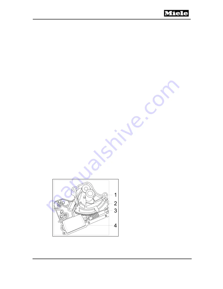
Figure 035-1:
Pinch/Drain Valve
The motor drives a cog wheel segment that pinches the hose closed. A
microswitch registers if the hose is open. When the motor is activated to
1
Hose
2
Microswitch
3
Cog wheel segment with guide rail
4
Motor
Summary of Contents for DGC 6 Series
Page 1: ...TECHNICAL INFORMATION DGC 6xxx Combi Steam Ovens 2018 Miele USA ...
Page 15: ...Technical Information 15 DGC 6xxx 010 Casing ...
Page 23: ...Technical Information 23 DGC 6xxx 020 Door ...
Page 27: ...Technical Information 27 DGC 6xxx 030 Cavity ...
Page 43: ...Technical Information 43 DGC 6xxx 035 Steam Generator Convection Fan ...
Page 57: ...Technical Information 57 DGC 6xxx Figure 035 14 Terminal Block ...
Page 58: ...Technical Information 58 DGC 6xxx 040 Water Container Drive ...
Page 68: ...Technical Information 68 DGC 6xxx 045 Air Duct Power Electronic ...


