Technical Information
8
DGC 6xxx
Figure 045-19: Screws Securing Distributors, Position Switch Mounting Bracket and Air
Duct ................................................................................................................................. 89
Figure 045-20: Roast Probe Electronic ........................................................................... 90
Figure 045-21: Wireless Roast Probe Test Setup ........................................................... 90
Figure 060-1: M-Touch Display ....................................................................................... 92
Figure 060-2: Rapid Heat-Up (R13 and R15 Alternately) ............................................... 94
Figure 060-3: Convection ................................................................................................ 94
Figure 060-4: Surround ................................................................................................... 95
Figure 060-5: Bake .......................................................................................................... 95
Figure 060-6: Browning ................................................................................................... 95
Figure 060-7: Convection Broil, Broil .............................................................................. 95
Figure 060-8: Eco Broil ................................................................................................... 95
Figure 060-9: Rotating the Drain Filter .......................................................................... 103
Figure 060-10: Fascia Panel Cover .............................................................................. 117
Figure 060-11: Fascia Panel/Control Electronic Assembly ........................................... 117
List of Tables
Table C-1: Appliance Information .................................................................................... 10
Table 030-1: Heater Element Data ................................................................................. 28
Table 030-2: Oven Light Data ......................................................................................... 28
Table 030-3: Heat-Flow Temperature Sensor Resistance Chart .................................... 28
Table 035-1: Air Flap Motor Data .................................................................................... 44
Table 035-2: Cavity Temperature Sensor Data .............................................................. 44
Table 035-3: Steam Generator Heater Data ................................................................... 44
Table 035-4: Steam Generator Temperature Regulator Data ......................................... 44
Table 035-5: Convection Fan Data ................................................................................. 44
Table 035-6: Drain Pump Data ....................................................................................... 44
Table 040-1: Lift Motor Data ........................................................................................... 59
Table 045-1: Cooling-Fan Data ....................................................................................... 69
Table 045-2: Heat-Flow Fan Data ................................................................................... 69
Table 045-3: Feed Pump Data ........................................................................................ 69
Table 045-4: Inlet Valve Data .......................................................................................... 69
Table 045-5: Fan Run-On Data ....................................................................................... 70
Table 060-1: Melodies for Appliances with Loudspeaker ................................................ 94
Table 060-2: Operating-Mode Overview ......................................................................... 96
Table 060-3: Descaling Counter versus Water Hardness ............................................. 107
Table 060-4: Settings Menu .......................................................................................... 112
Table 060-5: Programming Functions ........................................................................... 113
Table 060-6: Service Mode Functions .......................................................................... 116
Summary of Contents for DGC 6 Series
Page 1: ...TECHNICAL INFORMATION DGC 6xxx Combi Steam Ovens 2018 Miele USA ...
Page 15: ...Technical Information 15 DGC 6xxx 010 Casing ...
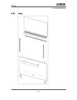
Page 23: ...Technical Information 23 DGC 6xxx 020 Door ...
Page 27: ...Technical Information 27 DGC 6xxx 030 Cavity ...
Page 43: ...Technical Information 43 DGC 6xxx 035 Steam Generator Convection Fan ...
Page 57: ...Technical Information 57 DGC 6xxx Figure 035 14 Terminal Block ...
Page 58: ...Technical Information 58 DGC 6xxx 040 Water Container Drive ...
Page 68: ...Technical Information 68 DGC 6xxx 045 Air Duct Power Electronic ...


