Technical Information
29
H 408x BM
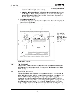
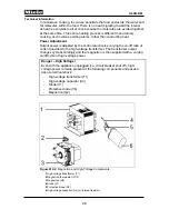
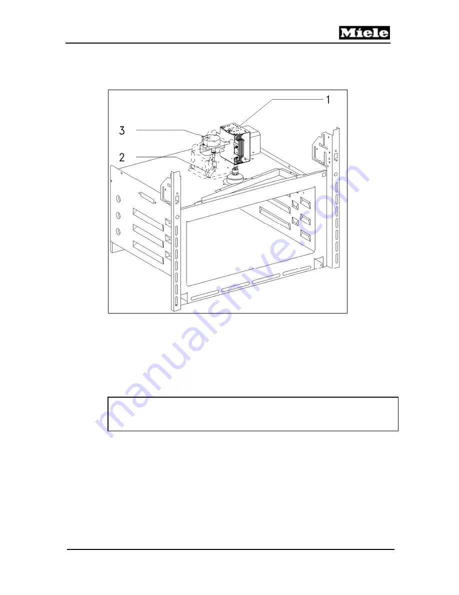
The magnetron (Figure 012-3, Item 1) supplies microwave energy from above
into the oven cavity. A wave guide (Figure 012-3, Item 2) driven by a motor
(Figure 012-3, Item 3) distributes the microwave energy.
Figure 012-3:
Microwave Components
4
Service
4.1
Front Air Duct Removal
(up to Machine No. 10/59114003)
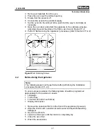
1. Remove the appliance from its cabinet; see Section 011-4.3.
2. Remove the screws securing the appliance lid. Remove the lid.
Danger!
Before performing any service or repair work, discharge the high-voltage
capacitor. See Section A-2.
3. Remove the fascia panel. See Section 040-4.5.
4. Remove the door spring. See Section 011-4.6.
5. Remove the support plate. See Section 040-4.7.
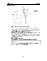
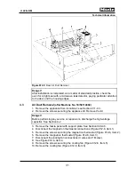
6. Remove the screws securing the release element (Figure 012-4, Item 1).
7. Remove the release element (Figure 012-4, Item 2).
8. Remove the screws securing the air duct panel (Figure 012-4, Item 3).
9. Remove the air duct panel (Figure 012-4, Item 4).
10. Disconnect the magnetron connections (Figure 012-4, Item 5).
11. Remove the screws securing the front air duct (Figure 012-4, Item 6).
12. Remove the front air duct (Figure 012-4, Item 7).
Summary of Contents for H 4080 BM
Page 1: ...TECHNICAL INFORMATION H 408x BM Speed Ovens 2013 Miele USA ...
Page 15: ...Technical Information 15 H 408x BM 011 Casing Door Lock ...
Page 25: ...Technical Information 25 H 408x BM 012 Air Duct Magnetron ...
Page 43: ...Technical Information 43 H 408x BM 020 Door ...
Page 47: ...Technical Information 47 H 408x BM 031 Oven Cavity Wave Distribution ...
Page 52: ...Technical Information 52 H 408x BM 032 Convection Fan Heaters ...
Page 58: ...Technical Information 58 H 408x BM 040 Control Panel Electrical System ...


