Technical Information
35
H 408x BM
the two terminals of the magnetron (filament). The ohmmeter has to be
able to measure in the milliohm (m
Ω
) range, and the reading must be less
than one ohm (1
Ω
).
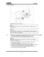
Danger!
After installation is completed, as a matter of standard practice, check the
oven for a tight seal with a microwave leak detector, paying particular attention
to the door and the housing edges.
4.8 Magnetron
Test
1. Remove the appliance from its cabinet; see Section 011-4.3.
2. Remove the screws securing the appliance lid. Remove the lid.
Danger!
Before performing any service or repair work, discharge the high-voltage
capacitor. See Section A-2.
3. Disconnect both magnetron connections.
4. Using an ohmmeter (per IEC 6557-2) with a measuring capability of at
least 500 volts, measure the resistance between one of the two terminals
and the metal housing of the magnetron.
5. The reading must be infinite
∞
.
6. Repeat the check for the second terminal.
Danger!
After installation is completed, as a matter of standard practice, check the
oven for a tight seal with a microwave leak detector, paying particular attention
to the door and the housing edges.
4.9
Magnetron (G2) Removal
1. Remove the appliance from its cabinet; see Section 011-4.3.
2. Remove the screws securing the appliance lid. Remove the lid.
Danger!
Before performing any service or repair work, discharge the high-voltage
capacitor. See Section A-2.
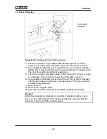
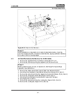
3. Disconnect the magnetron thermostat connections (Figure 012-6, Item 1).
4. Remove the screws securing the magnetron thermostat (Figure 012-6, Item 2).
5. Remove the magnetron thermostat (Figure 012-6, Item 3).
6. Disconnect the cooling fan connections (3 wires and 1 Molex). See Figure 012-6,
Item 4.
7. Remove the screws securing the cooling fan (Figure 012-6, Item 5).
8. Remove the cooling fan (Figure 012-6, Item 6).
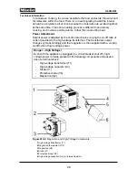
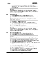
9. Remove the four T20 screws securing the air duct (Figure 012-7, Item 1).
10. Push in on the air duct retaining notches (Figure 012-7, Item 2).
11. Lift the air duct upwards to release it.
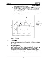
12. Remove the four 8mm locknuts securing the magnetron (Figure 012-10).
13. Cut the ducting covering the magnetron at the score marks.
14. Pull the magnetron out of the wave distributor housing.
Summary of Contents for H 4080 BM
Page 1: ...TECHNICAL INFORMATION H 408x BM Speed Ovens 2013 Miele USA ...
Page 15: ...Technical Information 15 H 408x BM 011 Casing Door Lock ...
Page 25: ...Technical Information 25 H 408x BM 012 Air Duct Magnetron ...
Page 43: ...Technical Information 43 H 408x BM 020 Door ...
Page 47: ...Technical Information 47 H 408x BM 031 Oven Cavity Wave Distribution ...
Page 52: ...Technical Information 52 H 408x BM 032 Convection Fan Heaters ...
Page 58: ...Technical Information 58 H 408x BM 040 Control Panel Electrical System ...


