

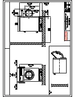
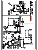
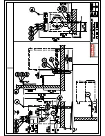
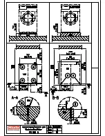
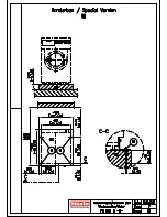
Installation plan PW 6131 Steam
Date 19.10.2007
Page
9
USA CDN
Max. temperature
203 °F
95 °C
Machine drain connection (d
a
× s × l)
3" x 1/16" x 3 9/16" 75×1,9×90 mm
On-site drain connection (d
i
)
3"
75 mm
Drainage via
dump valve
Max. throughput
52.8 gal/min
200 l/min
Vented drainage required. If ventilation is insufficient, fit
Miele kit, Mat. no. 05238090.
Drain manifolds serving several machines must be of
sufficient cross-section.
Foam vent
A drainage system for foam escaping from the drain
vent can be built using standard drain pipe sections.
A 87° branch with an end cap should be provided for
this purpose.
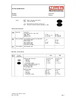
Miele plinth UG/UO 6013
Fittings (supplied)
4 × metal angled brackets (to secure machine to plinth)
4 × screws (Diameter × length)
5/16" x 3 1/8"
8 × 80 mm
4 × wall anchors (Diameter × length)
1/2" x 2 3/8"
12 × 60 mm
Machine must be secured!
Fixing materials provided for securing to concrete floor
On concrete platform
2 × screws (Diameter × length)
5/16" x 3 1/8"
8 × 80 mm
2 × wall anchors (Diameter × length)
1/2" x 2 3/8"
12 × 60 mm
Machine must be secured!
Fixing materials provided for securing to concrete floor
Without
plinth
2 × screws (Diameter × length)
5/16" x 3 1/8"
8 × 80 mm
2 × wall anchors (Diameter × length)
1/2" x 2 3/8"
12 × 60 mm
Machine must be secured!
Fixing materials provided for securing to concrete floor
On concrete platform
4 × screws (Diameter × length)
5/16“ x 3 1/8“
8 × 80 mm
4 × wall anchors (Diameter × length)
1/2“ x 2 3/8“
12 × 60 mm
Machine must be secured!
Fixing materials provided for securing to concrete floor
Without plinth
4 × screws (Diameter × length)
5/16“ x 3 1/8“
8 × 80 mm
4 × wall anchors (Diameter × length)
1/2“ x 2 3/8“
12 × 60 mm
Machine must be secured!
Special product
WI:
Fixing materials provided for securing to concrete floor
Machine data
Width
31 5/8”
804 mm
Depth
35 13/16"
910 mm
Height
49 3/16"
1.250 mm
Knocked-down dimensions (Width)
31 7/8"
810 mm
Recommended clearance to rear wall
(to machine front edge)
63" 1.600
mm
Net weight
763 lbs
346 kg
Dynamic floor load during operation, max.
4,304 N
4.304 N
Static load, max.
3,801 N
3.801 N
Dynamic load max.
503 N
503 N
Drum frequency, max.
18.3 Hz
18,3 Hz
Average heat dissipation
(depending on room temperature and selected program)
1,470 W
1.470 W
Installation should only be carried out by authorized installers in accordance with all local and national regulations!
Observe installation instructions when installing machine! All rights reserved!


