


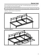
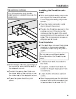


Spacer bars
57
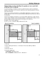
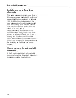
When installing several SmartLine elements, an additional spacer bar must be fit-
ted in between the individual elements.
The clips supplied with the spacer bars are only required for installing the CSDA.
Installing 3 elements and 2 spacer bars
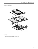
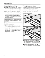
Onset installation
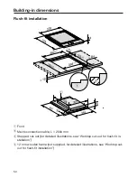
Flush-fit installation
Summary of Contents for SmartLine CS 7632
Page 49: ...Building in dimensions 49 Onset installation a Front b Mains connection cable L 2000 mm ...
Page 64: ......
Page 65: ......
Page 66: ......


