11
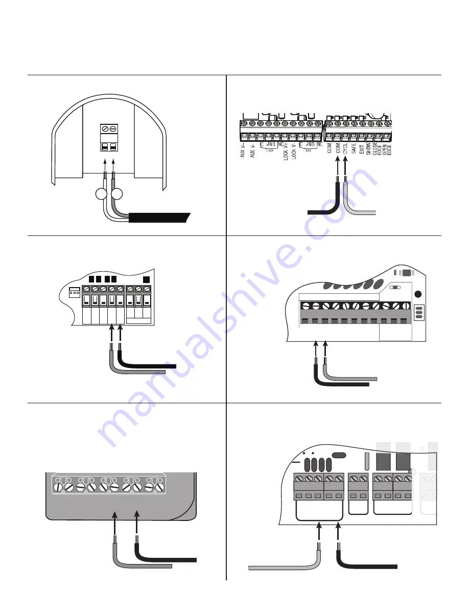
Connect
#2
wire from the
RELAY
OUTPUT
terminals on the keypad to
the
COM
terminal on the gate opener
control board.
Connect
#1
wire from the
RELAY OUTPUT
terminals
on the keypad to the
CYCLE
terminal on the
gate opener control board.
#2
#1
Control Board Connection Examples
NOTE:
If your control board doesn’t look like any of these diagrams, please refer to the opener’s instruction manual to locate the control board
input . Generally, the OUT wire should connect to the CYCLE terminal on the control board while COM connects to the COMMON terminal .
Connect
#2
wire from
the keypad to the
COM
terminal on the gate
opener control board.
Connect
#1
wire from the
RELAY OUTPUT
terminals
on the keypad to the
CYCLE
terminal on the
gate opener control board.
#2
#1
POWER
ON OFF
K1
06
D1
C2
C7
C15
LED3
D15
R20
IC4
D16
D13
D14
K2
BA
TT
- BA
TT+
EDGE
COM
LOCK+
LOCK -
M_BLK
M_RED
VAR2
GRN
VAR3
VAR3
VAR1
VAR4
VAR5
PF1
VAR6
WHT
CYCLE
EXIT
SAFETY
COM
CHGR
CHGR
RECR
GRN
BLK
RED
EXIT
SAFETY
EDGE
CY
CLE
COMMON
LINK
Connect
#1
wire from the
RELAY OUTPUT
terminals
on the keypad to
CYCLE
terminal on the gate opener
control board.
Connect
#2
wire from the
RELAY
OUTPUT
terminals on the keypad
to the
COMMMON
terminal on
the gate opener control board.
#1
#2
RECEIVER
ALM
RCVR.
COM
GRN
BLK
RED
CYCLE
SAFETY
EXIT
SHADOW
OPEN EDGE
COM
CONTROL INPUTS
CLOSE EDGE
Connect
#1
wire from
the
RELAY OUTPUT
terminals on
the keypad to
CYCLE
terminal on
the gate opener control board.
Connect
#2
wire from the
RELAY OUTPUT
terminals
on the keypad to the
COM
terminal on the gate opener
control board.
#1
#2
Connect
#1
wire from the
RELAY OUTPUT
terminals
on the keypad to
CYCLE
terminal on the gate opener
control board.
Connect
#2
wire from the
keypad to the
COMMON
terminal on the gate opener
control board.
#1
#2
V
AR5
K1
PF1
K2
B
A
T
T
+
K3
K4
V
AR4
V
AR3
V
AR2
V
AR1
P
W
R
.
SF
TY
.
EXIT
C
YCLE
EDGE
SENSOR
COMMON
LOCK+
LOCK–
WHT
GRN
RED
BLK
WHT
GRN
SECOND OPR.
FIRST OPR.
RED
BLK
14
VAC OR
SOLAR
Mighty Mule MM371, MM372, MM571 and
MM572 Control Boards
MM271 Control Boards
Mighty Mule 360 Control Board
Keypad Terminal Wiring for Reference
MM560, MM562, MM660, PRO3000XLS Series
and PRO4000XLS Series Control Boards
MM262, MM362, MM462, FM202
PRO-SW2000XLS Series Control Boards
Figure 9
OUT
COM
Hard-wire from Gate Opener
#
1
#
2
Summary of Contents for FM137
Page 14: ...14 Notes ...
Page 15: ...15 Notes ...


