background image

22.

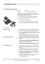
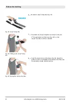
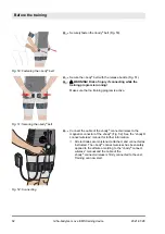
Securely fasten the i-body

®

 belt (Fig. 50).

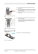
23.

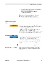
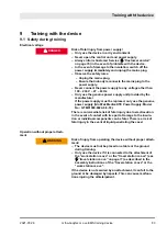
Secure the i-body

®

 belt with the release buckle (Fig. 51).

24.

L

 WARNING! Risk of injury if connecting while the

training program is running!

Make sure that no training program is active.

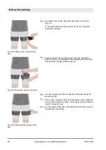
25.

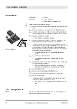
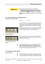
Connect the cable of the i-body

®

 connect wireless to the

magnetic connector of the i-body

®

 (Fig. 52). See the “i-body®

connect wireless” manual for further information.

ð

All electrodes are moistened, attached, and connected as
instructed. The i-body

®

 connect wireless has been safely

applied to the athlete according to the “i-body

®

 connect

wireless” manual and the cable of the
i-body

®

 connect wireless is firmly connected to the vest.

Training can now start.

Fig. 50: Fastening the i-body

®

 belt

Fig. 51: Securing the i-body

®

 belt

Fig. 52: Connecting

 Before the training

2021-07-28

miha-bodytec m.ove EMS training device

82

Summary of Contents for bodytec m.ove

Page 1: ...miha bodytec m ove Operating instructions US ...

Page 2: ...ytec Inc 2171 Executive Drive Suite 200 Addison Illinois 60101 USA Telephone 1 833 367 6442 E mail usa miha bodytec com Internet www miha bodytec us This manual was created by kothes GmbH Internet www kothes com TD150168 Rev 0 2021 07 28 miha bodytec m ove EMS training device 2 ...

Page 3: ...ons for the prevention of acci dents and the general safety regulations for the location in which the device is used also apply The illustrations in this manual provide a basic understanding and may vary from the actual design Safety instructions Safety instructions in this manual are identified by symbols The safety instructions are introduced by signal words which express the extent of the hazar...

Page 4: ... steps References to sections of this manual and to other applicable documents Lists without a defined sequence Button Controls e g buttons switches display elements e g signal lamps Display Screen elements e g buttons assignment of function keys The following document applies in addition to this manual n User manual for i body connect wireless n Installation manual for travel station m ove n Inst...

Page 5: ... 5 Basic information on EMS training 48 5 1 Safety first 48 5 2 EMS training 48 5 3 Training frequency and regeneration 49 6 Understanding the device 52 6 1 Explanation of terms 52 6 2 Opening menu tabs 55 6 3 Opening menus 56 6 4 Entering text 59 7 Customization and setup 61 7 1 Adjusting the device setup 61 7 2 Selecting the language 62 7 3 Program memory settings 63 7 4 Setting up the training ...

Page 6: ...lans 89 10 5 Training 94 10 6 Transponder system 98 10 7 Training with synchronized start 102 11 After the training 103 11 1 Taking off electrodes 103 11 2 Cleaning and storage 104 11 2 1 Cleaning the i body and the individual elec trodes 104 11 2 2 Cleaning the external cables 106 11 2 3 Cleaning the control unit 107 12 Packaging and storage 108 12 1 Symbols on the packaging 108 12 2 Transport an...

Page 7: ...ses Complete body training which addresses all muscle groups is possible with up to 10 pairs of electrodes During conventional training electrical signals from the brain ini tiate contractions and thus movement of the muscles With EMS electrical pulses from outside activate the muscles It makes no dif ference to the muscle whether electrical stimuli are sent from the brain or from electrodes It re...

Page 8: ...ttle stress on the joints n Deeper muscle groups can be easily reached n The training is very intense and thus short 10 20 minutes Fig 2 Control unit top side 1 Level controller for legs 2 Level controller for buttocks 3 Level controller for lower back 4 Level controller for upper back 5 Level controller for side back 6 Level controller for abdomen 7 Level controller for chest 8 Level controller f...

Page 9: ...sing the i body straps flex The two level controllers without any assigned body parts Fig 2 9 10 do not have any function If a transponder card is placed on the transponder card contact surface Fig 2 12 the settings stored on this card can be edited or loaded automatically Ä Chapter 10 6 Transponder system on page 98 The multi function button Fig 2 13 is used for navigating through the menus and f...

Page 10: ...be inserted into the USB port Fig 3 3 for performing updates and for saving device set tings The rechargeable battery Fig 3 4 located in a designated rechargeable battery compartment incl connector is used to supply power without a power supply during mobile use 1 2 Equipment Using equipment not obtained from miha bodytec or authorized dealers represents an increased safety risk Only use genuine m...

Page 11: ...nit when in mobile use For further information please refer to TD 15303 Installation instructions for travel station m ove Rechargeable battery for m ove Fig 4 Rechargeable battery for m ove travel station m ove Fig 5 travel station m ove Overview and scope of delivery 2021 07 28 miha bodytec m ove EMS training device 11 ...

Page 12: ... for work station m ove Wireless stimulation unit that can be attached to the body of the athlete for wireless training via a Bluetooth connection See the i body connect wireless manual for further information work station m ove Fig 6 work station m ove i body connect wireless Fig 7 i body connect wireless Overview and scope of delivery 2021 07 28 miha bodytec m ove EMS training device 12 ...

Page 13: ...vest for applying electrodes to the upper body Table 1 Electrode sizes for each vest size Vest size Size 1 and size V1 Size 2 size 3 and size V2 in in 2 electrodes for abdomen 22 85 in 27 56 in 2 electrodes for chest 10 31 in 12 81 in i body connect charger Fig 8 i body connect charger Transponder card Fig 9 Transponder card i body Fig 10 i body Overview and scope of delivery 2021 07 28 miha bodyt...

Page 14: ...aps flex Electrode size Size 1 pair 16 74 in each Size 2 pair 20 77 in each Size 3 pair 29 14 in each Buttocks electrode hereinafter referred to as i body belt for applying to the buttocks Table 3 Electrode sizes for each i body belt size Size of the i body belt Electrode size Size 1 2 buttocks electrodes each 14 7 in Size 2 2 buttocks electrodes each 18 34 in i body straps flex Fig 11 i body stra...

Page 15: ...p spray bottle for moistening the electrodes The miha bodytec USB flash drive is delivered with the device and serves as a data carrier for performing updates as well as saving and transferring settings i body cable Fig 13 i body cable Undergarments Fig 14 Undergarments Pump spray bottle Fig 15 Pump spray bottle miha bodytec USB flash drive Overview and scope of delivery 2021 07 28 miha bodytec m ...

Page 16: ... our headquarters Address miha bodytec Inc 2171 Executive Drive Suite 200 Addison Illinois 60101 USA Telephone 1 833 367 6442 E mail usa miha bodytec com Website www miha bodytec us We are also always interested in information and experience arising from the use of the device which can be valuable for the improvement of our product Customer service Overview and scope of delivery 2021 07 28 miha bo...

Page 17: ...suse muscle atrophy The miha bodytec m ove electrical impulses allow the triggering of action potentials on motoneurons of motor nerves excitations These excitations of motoneurons are transmitted to the muscle fibers via the motor endplate where they generate mechanical muscle fiber responses that correspond to muscle work Depending on the parameters of the electrical impulses pulse fre quency du...

Page 18: ...cause car diac arrhythmias Stimulation must not be applied transcerebrally Stimulation must not be applied over swollen infected or inflamed areas or skin eruptions e g phlebitis thrombo phlebitis varicose veins etc Stimulation must not be applied over or in proximity to cancerous lesions Whenever using the device start with an intensity level of 0 and increase slowly Ensure basic tension in the m...

Page 19: ...on is pre sent do not use the device In the event of doubts consult a doctor before the first or any further trainings If you are taking medication consult a doctor before the first or any further trainings The presence of certain physical conditions can result in a risk of injuries or even death The existence of such a physical condition is referred to as contraindication The device must not be u...

Page 20: ...for them with truthful information on current health restrictions e g fever Athletes patients make sure that none of the listed contraindica tions Ä Chapter 2 3 Risks due to physical condition Contraindi cations on page 19 apply to them before they start with the training Trainer The trainer must have taken part in a basic miha bodytec training session and can prove their qualification by presenti...

Page 21: ...o risks can be eliminated During a workout the trainer and the athletes patients must have unimpeded access to the device s control elements They must be able to use and regulate the device easily quickly and with preci sion The full attention of the trainer is required at all times during the workout If this cannot be ensured the trainer must reduce the main intensity level of the device athlete ...

Page 22: ...ia that can be attributed to training with the device Since a theoretical residual risk remains strictly observe the instructions below Persons affected will lose consciousness after a brief period of time Health risk due to cardiac arrhythmia Never exercise by yourself Always ensure that a qualified trainer is paying attention and can intervene in the event of an emergency Act immediately if the ...

Page 23: ...rechargeable battery from the manu facturer It is available from Customer Service If the rechargeable battery needs to be replaced use only the genuine rechargeable battery Battery Pack miha bodytec m ove model no RRC2054 2 For information on how to replace the rechargeable battery please contact Customer Service Ä Customer service on page 16 There is an immediate risk of fatal injury due to elect...

Page 24: ...the device and the wall connection with a cable bridge Improper routing of connection cables can lead to trip hazards or strangulation of babies and toddlers children as well as handicapped persons Risk of injury if detaching or connecting electrode cables during operation Start by making sure that no training program is active Ä Opening the main menu on page 58 then connect or detach the electrod...

Page 25: ...o not store batteries in a discharged state for more than 1 month Do not store batteries for more than 1 year without charging them Misuse or improper storage of the lithium ion battery can cause dangerous situations Risk of injury from improper hygienic cleaning of the control elements of the device and equipment Properly clean the control elements of the device and the equipment used after train...

Page 26: ...nciple of EMS and the effects on the body must be known Children are not allowed to train or play with the device or perform cleaning or maintenance tasks Handling the device without training instruction can result in dangerous situations that can be fatal Each trainer must take part in a training session held by the manufacturer before using the device and each athlete patient must have been inst...

Page 27: ... m ove can be very heavy this can cause serious injuries Risk of injuries from incorrect spare parts and unsuitable accessories Never make changes to the device Never establish connections with other devices not described in this manual Never connect parts other than genuine parts from miha bodytec Only operate the device in combination with the work sta tion m ove or the travel station m ove Neve...

Page 28: ...ma or fracture Following recent surgical procedures where muscle con traction may disrupt the healing process Over areas of the skin which lack normal sensation Risk of injury from improper maintenance or repair Never perform unauthorized repairs of the device In case of defects on the device contact Customer Service Ä Customer service on page 16 Only perform the maintenance tasks described in thi...

Page 29: ...biologic products medical devices dietary supplements infant formula and cosmetics If you think you or someone in your family has experienced a serious reaction to a medical product you are encouraged to take the reporting form to your doctor Your health care provider can provide clinical information based on your medical record that can help FDA evaluate your report However we understand that for...

Page 30: ...fety Signs Reg istered Safety Signs Including AMEND MENT 1 2012 Through AMEND MENT 7 2016 Not for persons with pacemakers or implanted defibrillators The device must never be used by persons with cardiac pace makers or other active medical implants In this connection also observe the contraindi cations ES60601 1 2005 R 2012 And A1 2012 Table D 2 Symbol 10 Medical electrical equipment Part 1 Genera...

Page 31: ...European technical con formity n Mandatory sign IEC protection Class II n Mandatory sign RX only n Mandatory sign CAN ICES 3 B NMB 3 B Compliance with Canadian ICES 3 Rules n Mandatory sign FCC marking Compliance with part 15 of the FCC Rules Federal law restricts this device to sale by or on the order of a practitioner licensed by the law of the State in which he she practices to use or order the...

Page 32: ...ition 2016 11 01 Clause 5 1 7 Medical Devices Symbols To Be Used With Medical Device Labels Labelling And Information To Be Supplied Part 1 General Require ments Serial number Indicates the manufac turer s serial number so that a specific device can be identified ES60601 1 2005 R 2012 And A1 2012 Table D 1 Symbol 4 Medical electrical equipment Part 1 General require ments for basic safety and esse...

Page 33: ...t in accordance with Article 11 2 of Directive 2002 96 EC WEEE Recycle Elec tronic Equipment Waste of electrical and electronic equipment WEEE Electrical and electronic parts may contain toxic materials These parts must be collected separately and turned in at com munal collection points or disposed of by a specialist company ISO 15223 1 Third Edition 2016 11 01 Clause 5 1 5 Medical Devices Symbol...

Page 34: ...rds Indicates the compli ance with the exemp tion from the routine evaluation limits in sec tion 2 5 of RSS 102 and with RSS 102 RF exposure for Class B digital devices 2 7 3 Cleaning symbols Symbol Standard Reference Standard Title Symbol Title Explanatory Text 7000 Fifth Edition 2014 01 15 3125 Graphical Symbols For Use On Equip ment Registered Symbols Wash by hand Hand wash only 7000 Fifth Edit...

Page 35: ...h environmental regulations from local municipal authorities or specialized disposal companies Environmental hazards can be caused by incorrect disposal The device must not be disposed of via domestic waste Recycle dismantled components n Have metals turned into scrap n Recycle plastic elements n Sort and dispose of all other components according to material condition Electronic components such as...

Page 36: ...e miha bodytec m ove s electrical impulses allow the trig gering of action potentials on motoneurons of motor nerves excitations These excitations of motoneurons are trans mitted to the muscle fibers via the motor endplate where they generate mechanical muscle fiber responses that cor respond to muscle work Depending on the parameters of the electrical impulses pulse frequency duration of contrac ...

Page 37: ...tput voltage at 500 ohm 300 mJ 50 mA 500 mJ Permissible ambient temperature operation 40 F 105 F 5 C 40 C Permitted battery charging temperature 32 F 113 F 0 C 45 C Time for warming up the device from the lowest storage temperature 4 F 20 C up to operating temperature for intended use of 68 F 20 C ambient temperature 10 hours Time for cooling down the device from the maximum permissible storage te...

Page 38: ...ion class Protective insulation II Protection class II equipment has an increased or dual insu lation at the level of the rated insulation voltage between active and touchable parts In most cases they are not con nected to the protective conductor Transponder card RFID 13 56 MHz according to ISO IEC 14443 Mifare Classic 4k can be formatted on the device Synchronized start 2 4 GHz M2M wireless mesh...

Page 39: ...systems used in the home healthcare environment n IEC 62304 2015 Medical device software Software life cycle processes n ISO 14971 2007 Medical devices Application of risk man agement to medical devices n IEC 62366 1 2015 Medical devices Part 1 Application of usability engineering to medical devices n ISO 10993 1 2009 Biological evaluation of medical devices Part 1 Evaluation and testing within a ...

Page 40: ...comply with Innovation Science and Economic Development Canada s licence exempt RSS s Operation is subject to the following two conditions 1 This device may not cause interference 2 This device must accept any interference including interference that may cause undesired operation of the device Le dispositif rencontre l exemption des limites courantes d évalua tion dans la section 2 5 de RSS 102 et...

Page 41: ...source software license terms which we will gladly send you upon request The open source software is provided free of charge You can request the source code for up to three years from the purchase date of the device if provided in the relevant open source software license terms Any liability for the use of the open source software beyond the program cycle provided by us for the product as well as ...

Page 42: ...m ove device is suitable for usage in any building including residential buildings and those connected up direct to low voltage power supply networks installed for residential buildings Harmonic distortion IEC 61000 3 2 Class A Voltage fluctuations and flicker IEC 61000 3 3 Complies Guidance and manufacturer s declaration electromagnetic immunity The miha bodytec m ove EMS training device has been...

Page 43: ...uipment IEC 61000 4 3 385 MHz 27 V m 450 MHz 28 V m 710 MHz 9 V m 745 MHz 9 V m 780 MHz 9 V m 810 MHz 28 V m 870 MHz 28 V m 930 MHz 28 V m 1720 MHz 28 V m 1845 MHz 28 V m 1970 MHz 28 V m 2450 MHz 28 V m 5240 MHz 9 V m 5500 MHz 9 V m 5785 MHz 9 V m 385 MHz 27 V m 450 MHz 28 V m 710 MHz 9 V m 745 MHz 9 V m 780 MHz 9 V m 810 MHz 28 V m 870 MHz 28 V m 930 MHz 28 V m 1720 MHz 28 V m 1845 MHz 28 V m 197...

Page 44: ...th a maximum cable length of 3 meters or more Guidance and manufacturer s declaration electromagnetic immunity The miha bodytec m ove EMS training device has been designed for use in electromagnetic environments as outlined below The buyer or user of the miha bodytec m ove device shall make sure that the device is used under such conditions Immunity test IEC 60601 test level Compliance level Elect...

Page 45: ...tion dis tance d in m to a RF communications equip ment with a maximum power P in W can be cal culated using the equa tion in clause 8 10 of IEC 60601 1 2 d 6 E P Voltage dips IEC 61000 4 11 0 UT 0 5 cycle at 0 45 90 135 180 225 270 and 315 0 UT 1 cycle 70 UT 25 30 cycles Single phase at 0 0 UT 0 5 cycle at 0 45 90 135 180 225 270 and 315 0 UT 1 cycle 70 UT 25 30 cycles individual phase at 0 Mains...

Page 46: ...alers For replaceable parts available see Ä Chapter 1 2 Equipment on page 10 Using other cables or equipment can void the authority to operate the equipment In the presence of an electromagnetic disturbance the electronic muscle stimulation EMS operates as intended In case of voltage interruptions continuous operation is not guar anteed If continuous operation is required an uninterruptible power ...

Page 47: ...ables and external antennas must be used no closer than 30 cm 12 inches to any part of the miha bodytec m ove EMS training device including cables speci fied by the manufacturer Otherwise degradation of the per formance of this equipment can result NOTICE Electromagnetic compatibility 2021 07 28 miha bodytec m ove EMS training device 47 ...

Page 48: ...With EMS electrical pulses from outside acti vate the muscles It makes no difference to the muscle whether electrical stimulations are sent from the brain or from electrodes It reacts by contracting Special features and benefits n All muscle groups can be activated using an electrode system with up to 10 pairs of electrodes n Static and dynamic training with interaction of deliberate muscle contra...

Page 49: ...hes increased resting and active pulse rate muscle and tendon pains and also depression among other things The recommended training frequency is 1 2 times per week Do not train in the event of severe muscle ache feeling unwell or other contraindications Ä Never exercise if on page 19 Danger to health from EMS training if performed while ill or otherwise fatigued If ill only train after consulting ...

Page 50: ... replenish your body s reserve of carbohydrates This can be done by eating a meal high in carbohy drates but not heavy 2 3 hours before a workout Your body also requires adequate fluids Drink 500 ml before and after a workout to replenish your hydration levels Training close to your physical limit can initially lead to extremely elevated levels of creatine kinase and myoglobin especially during th...

Page 51: ...otein energy drink such as a protein shake for better regeneration and for stimulation of muscle building Take a break after the workout and do not complete any further workouts to guarantee best possible regeneration and to avoid overtraining Regeneration Basic information on EMS training 2021 07 28 miha bodytec m ove EMS training device 51 ...

Page 52: ...els can be automatically accessed on the transponder card during future workouts For this to work the Load level function must be active in the device settings In addition this option must also be set on the transponder card of the athlete patient When a workout is started with a transponder card in place level controllers 1 10 are automatically set to the saved levels To increase safety for the a...

Page 53: ...tor each person training To ensure that training with synchronized start is effective and safe a maximum of 2 persons training per trainer is recommended Risk of injury due to incorrect input of brand codes Never enter brand codes yourself If you want to use brand codes contact Customer Service Ä Customer service on page 16 If brand codes are entered without adequate background knowledge athletes ...

Page 54: ...g function must be used only under the guidance of miha bodytec service personnel The individual connections of the electrodes are assigned symboli cally to the level controllers The strength for the area is adjusted using the respective level controller Symbol Channels application area Channel 1 legs Channel 2 buttocks Channel 3 lower back Channel 4 upper back Channel 5 side back Channel 6 abdome...

Page 55: ...ge free Electrodes may be attached and detached from the device only when the device is in this safe condition Menu tabs Fig 19 1 offer convenient access to different configu ration options and special types of training sessions You can start navigating the available options with the help of menu tabs After selecting a menu tab you will be shown the associated menus or secondary menu tabs Main men...

Page 56: ...o the left next to the selected menu tab In the example shown tab A Fig 21 A is selected 6 3 Opening menus The device menus always have the same structure The status line displays the name of the menu Fig 22 1 The items of the respective menu Fig 22 3 are listed one below the other on the left side Fig 20 Selecting menu tabs Fig 21 Selected menu tab Structure of menus Fig 22 Structure of menus Und...

Page 57: ...cted Color Example Meaning Black background Menu can be selected Gray background Menu is locked Locked menus cannot be opened Colored back ground Menu is currently selected Gray background and colored frame Locked menu is currently selected The indicated color corresponds to the color selected in the Device color menu item By turning the multi function button only the position is shown 1 Turn the ...

Page 58: ...depends on the current device status The following cases are possible Open the main menu while a menu is displayed Ä From a menu on page 58 Open the main menu while a training session is active Ä During training on page 59 1 Turn the multi function button to select the top or bottom menu item 2 Press the multi function button to open the top or bottom menu item 3 Repeat steps 1 and 2 until the Mai...

Page 59: ...r card Data is written on the card and the programs or training plans saved on the card are dis played The main menu is only displayed after the card has been removed from the device 6 4 Entering text Fig 29 Entering text When creating customized settings or personal data you have the option to store information in text form e g Create customer card Name Fig 27 Main menu During training Fig 28 Mai...

Page 60: ...ntroller briefly Fig 29 12 the last letter in the text box is deleted When you keep it depressed the entire text box is deleted n When you turn the individual level controller Fig 29 1 10 channels 1 10 the letters are selected When you press the respective controllers they are adopted into the text box n When you press the multi function button Fig 29 11 the entered text is adopted Understanding t...

Page 61: ...e is being output n Pause transition color Specifies the color of the LED strip in the display and on the rear if a pause transition of more than 0 LEDs was selected n Pause transition Specifies how many LEDs are supposed to change color at the beginning of the pulse n Brightness Specifies the brightness of the display in the device n Language Specifies the language to be used for display texts n ...

Page 62: ... settings menu item ð The Device settings menu opens 3 Open the Language menu item 4 Select the desired language and confirm your selection by pressing the multi function button ð Display texts are shown in the language you have selected Every athlete patient can customize the language settings and store these personalized settings on the transponder card Ä Selecting individual language settings f...

Page 63: ...ue The pulse width is indicated in microseconds n Rise time Specifies the time that will elapse between the beginning of the pulse to the pulse reaching its peak n Save program Saves the program on the device Once saved a program can no longer be modified or deleted It can only be deactivated It will then only be displayed in the training plan memory settings and program memory settings The progra...

Page 64: ...ning time n Save training plan The training plan cannot be saved as long as the value of the remaining repetitions is not 0 Only training programs with 4 second cycles are displayed During training there will be a remaining time that elapses with no exercising if the training time cannot be divided by 8 seconds 4 second exercise 4 second pause If a training plan is deactivated it is no longer visi...

Page 65: ... a managed device n Group number Defines a group number for the training ses sion n Countdown Specifies the delay with which the training session will begin following the start command n Flexible training When the flexible training option is activated all participating devices only have to be set to the same cycle e g 4 s of pulse and 4 s of pause In addition the users of all devices must train us...

Page 66: ...group number must match the group number of the master device ð The device is ready to participate in the training session as a managed device All athletes also have to specify that they want to participate in the training with synchronized start session Ä Setting up the trans ponder card for training with synchronized start on page 100 7 6 Adjusting the favorites menu The favorites menu allows tr...

Page 67: ... device before switching to the Setup menu tab 1 Remove the service cover with the help of a screwdriver 2 Insert the miha bodytec USB flash drive into the USB port Fig 30 1 3 Open the Setup menu tab ð The Setup menu tab is opened 4 Use the multi function button to select the Data backup menu item and press the button to confirm your selection 5 Turn the multi function button to the left to set th...

Page 68: ... selection 7 Use the multi function button to select the Import training programs menu item and press the button to confirm your selection 8 You can use the selection box to define whether or not the training plans and programs stored in the backup files are supposed to be imported and applied Use the multi function button to select the YES or NO selection box and press the button to confirm your ...

Page 69: ...ter for viruses Computer viruses can change the update files This can result in errors in the control unit that affect the electrical outputs Interrupting the update process can cause material damage Do not disconnect the power supply during an update Do not switch off the device during an update Wait for the update to finish and do not input anything The device can be permanently damaged if it is...

Page 70: ...nd that the miha bodytec USB flash drive is fully inserted ð A prompt appears asking if you want to perform an update 6 Answer the prompt with Yes ð The update process starts This can take several minutes 7 Wait for the update do not disconnect the power supply and do not switch off the device ð After the update process is complete you will see a prompt to manually turn the device off and on again...

Page 71: ...to reset the device contact Customer Service Ä Customer service on page 16 7 12 Displaying statistics 1 Open the Setup menu tab ð The Setup menu tab opens 2 Use the multi function button to select the Statistics summary menu item and press the button to confirm your selection ð The Statistics summary menu opens You can view the following statistics in the Statistics summary menu n Device runtime o...

Page 72: ...s Ä Undergarments on page 15 Always pay attention to the correct size The undergarments must fit closely everywhere but must not cut into the skin or be too tight Pay attention that pants and shirt do not overlap under the elec trode areas on the abdomen and back Doubled fabric layers change pulse transfer making the actual workout different from what was planned Basically the sizes of the underga...

Page 73: ...cle fibers or shoulder dislocations Risk of injury due to damaged cables Check the cables and electrodes for damage before every workout Never use the device if cables or electrodes are damaged Training with damaged cables or damaged electrodes can lead to injuries Risk of injury from wearing accessories that are too small or too large Select the i body in accordance with the instructions Ä Choosi...

Page 74: ...it your arms and legs closely and do not dig in anywhere when closed The version information provides a guideline If i body straps flex never fit snugly when closed select a smaller size If the hook and eye cannot be closed select a larger size i body belts are available in 2 different versions i body belt version Size 1 Small 2 Large Select the i body belt so that the buttocks belt fits snugly on...

Page 75: ...s a sufficient distance to the control unit No water must penetrate the case There is a risk of fatal injury due to electrocution in the event of liquid penetrating the case of the control unit Do not use distilled water Do not exceed a water temperature of 86 F Only fill the pump spray bottle up to the max marking visible on the side Otherwise no pressure can be built up Pump air into the bottle ...

Page 76: ...orrect i body size on page 74 2 Spray the i body with water until a visible film of water has formed on the electrodes Fig 34 3 Put on the i body Close the fitting aid hook and loop in the area of the chest and abdomen in accordance with Fig 35 Moistening and applying electrodes Preparing the i body Fig 34 Moistening the i body Putting on the i body Fig 35 Wearing the i body Before the training 20...

Page 77: ...es it can be pulled into place on the fabric in the front and rear However never pull on the silicone on the side to smooth out the i body Fig 36 Closing the i body Fig 37 Smoothing out the i body Putting on and closing the i body straps flex arms Before the training 2021 07 28 miha bodytec m ove EMS training device 77 ...

Page 78: ...lex must face outwards 8 Insert the hook into one of the loops Fig 40 Adjust the width so that it is comfortable for the athlete and at the same time provides enough contact pressure Fig 38 i body straps flex Fig 39 Putting on the i body strap flex Fig 40 Closing the i body strap flex Before the training 2021 07 28 miha bodytec m ove EMS training device 78 ...

Page 79: ...e left arm 12 Connect both i body straps flex to the i body Fig 42 1 and 2 to the i body cable When connecting the i body straps flex always ensure that the corresponding cables medium length are used in accordance with Fig 42 13 Moisten 2 more i body straps flex Fig 43 Fig 41 Positioning the i body strap flex Fig 42 Connecting the i body straps flex Putting on and closing the i body straps flex l...

Page 80: ...n the i body strap flex so that the pushbutton faces for wards Fig 46 17 If the i body strap flex does not fit properly select a different loop to make it tighter or wider If necessary select a different i body straps flex size 18 Put the i body strap flex on the right leg in the same way as described for the left leg Fig 44 Putting on the i body strap flex Fig 45 Closing the i body strap flex Fig...

Page 81: ...es to the cables then put on the i body belt 21 Connect both electrodes of the i body belt to the i body Fig 49 to the i body cable When connecting the i body belt always ensure that the corresponding cables shortest length are used in accord ance with Fig 47 Fig 47 Connecting the i body straps flex Putting on and connecting the i body belt Fig 48 i body belt with buttocks electrodes Fig 49 Connec...

Page 82: ...body Fig 52 See the i body connect wireless manual for further information ð All electrodes are moistened attached and connected as instructed The i body connect wireless has been safely applied to the athlete according to the i body connect wireless manual and the cable of the i body connect wireless is firmly connected to the vest Training can now start Fig 50 Fastening the i body belt Fig 51 Se...

Page 83: ... GTM91099 6024 6 0 T2 There is an immediate risk of fatal injury due to electrocution in the event of contact with live parts Damage to the insula tion or individual components can be fatal There is a risk of fatal injury in the event of liquid penetrating the case Risk of injury from operating the device without proper attach ment The device must not be placed on a table or the ground during trai...

Page 84: ...2 Connecting the device Personnel n Trainer The control unit can be operated with or without a power supply unit The connection between the control unit and the person training is always wireless For more information see the i body connect wireless manual 1 Remove the connector cover of the electrical connection on the control unit Fig 53 1 Connect the magnetic plug of the power supply unit Fig 53...

Page 85: ...per right corner of the display Fig 54 When the power supply is connected the rechargeable battery is charged automatically This is indicated at the same place by an additional plug symbol Fig 55 If the rechargeable battery is used as intended and after approxi mately 300 discharge cycles per year it is recommended to replace the rechargeable battery after approximately 24 months For information o...

Page 86: ...differently to current intensity Therefore the current intensity must be regulated individually depending on the respective current sensitivity Training with the device 2021 07 28 miha bodytec m ove EMS training device 86 ...

Page 87: ...lse duration specifies the time in seconds s or milliseconds ms during which a current is output and the muscle is held in the shortened contracted condition The pulse frequency is displayed in Hertz Hz The pulse fre quency specifies how many individual pulses per second act on the muscles during the contraction phase n Each pulse results in a muscle contraction n The number of muscle contractions...

Page 88: ... 20 min 7 Hz Continuous 0 s 0 s 350 μs 5 Body relax 10 min 100 Hz 1 s 1 s 0 s 150 μs 6 Test training 12 min 85 Hz 4 s 4 s 0 4 s 350 μs The device uses bipolar pulses and supplies all channels equally during all programs Continuously emitted pulse to start off the workout The invigoration programs are used for muscle building and tight ening and strengthening the connective tissue and the skin At t...

Page 89: ...raining program has the identical parameters like the invigoration basic program The only difference is the length of the program and is therefore not to be regarded as another output mode It is ideal for starting EMS training thanks to its shorter length and gentle familiarization process For EMS beginners in particular it is important to follow the instructions on training fre quency and regener...

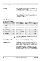
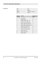
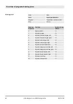
Page 90: ...ft 12 3 Dynamic forward lunges right 12 4 Dynamic diagonal crunches left 12 5 Dynamic diagonal crunches right 12 6 Dynamic knee compression 12 7 Dynamic body rotation left 12 8 Dynamic body rotation right 12 9 Dynamic crunches 12 10 Dynamic forward fold 12 11 Dynamic biceps 12 Training plan 1 Overview of programs training plans 2021 07 28 miha bodytec m ove EMS training device 90 ...

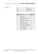
Page 91: ...verse diag onal left 12 3 Dynamic butterfly reverse diag onal right 12 4 Dynamic body rotation left 12 5 Dynamic body rotation right 12 6 Dynamic diagonal crunches left 12 7 Dynamic diagonal crunches right 12 8 Dynamic crunches 15 9 Dynamic overstretching 15 10 Dynamic forward fold 15 Training plan 2 Overview of programs training plans 2021 07 28 miha bodytec m ove EMS training device 91 ...

Page 92: ...ic forward lunges right 10 4 Dynamic side lunges left 10 5 Dynamic side lunges right 10 6 Dynamic knee compression 13 7 Dynamic diagonal crunches left 10 8 Dynamic diagonal crunches right 10 9 Dynamic body rotation left 10 10 Dynamic body rotation right 10 11 Dynamic crunches 13 12 Dynamic forward fold 13 Training plan 3 Overview of programs training plans 2021 07 28 miha bodytec m ove EMS trainin...

Page 93: ...ard lunges left 10 4 Dynamic forward lunges right 10 5 Dynamic side lunges left 10 6 Dynamic side lunges right 10 7 Dynamic diagonal crunches left 10 8 Dynamic diagonal crunches right 10 9 Dynamic crunches 13 10 Dynamic body rotation left 10 11 Dynamic body rotation right 10 12 Dynamic forward fold 13 Training plan 4 Overview of programs training plans 2021 07 28 miha bodytec m ove EMS training de...

Page 94: ...njury from incorrect program selection Only perform pre programming after extensive experience with EMS training Always be careful with pre programming Always check the program parameters Ä Chapter 10 Over view of programs training plans on page 87 Selecting an incorrect program according to its programming can result in injuries Before starting the application make sure that the rechargeable batt...

Page 95: ...n is not only used for choosing and con firming the programs but also as a stop button The training can be stopped at any time with the multi function button Turning up the intensity during the pulse pause is limited to 5 units both on the level controllers and the main controller Main controller If the Load level function is enabled the device is programmed such that the main controller cuts out ...

Page 96: ...wn in gray on the display and cannot be reactivated during the training ses sion If this happens even though something was connected to this channel remove the transponder card again right away at the start of the workout This ends the training session Next check to make sure that the contacts are properly connected and the electrodes are sufficiently moistened Correct the problem if necessary If ...

Page 97: ... main controller Fig 57 14 3 Confirm the desired program by pressing the multi function button Fig 57 13 4 Adjust the application time if necessary by turning the multi function button 5 Press the multi function button to start the program ð The time at the top right in the display starts running Working out Overview of programs training plans 2021 07 28 miha bodytec m ove EMS training device 97 ...

Page 98: ...the coming pulse type 10 If necessary adjust the pulse strength during the course of the training ð The pulses stop automatically after the completion of the program The program is ended prematurely by pressing the main controller 10 6 Transponder system Risk of injury if transponder cards are mixed up Always ensure that the correct transponder card is used Always check the program parameters Alwa...

Page 99: ...t surface 2 If the transponder card is still unformatted you will be prompted to format the transponder card Confirm the prompt by selecting YES using the multi function button 3 If the transponder card is empty the following question will be displayed Empty card Create customer card Confirm the prompt by selecting YES using the multi function button ð The system will automatically switch to the C...

Page 100: ...er card if a card is currently inserted in the device 2 Use the multi function button to select the Card management menu item 3 Place the transponder card on the designated contact sur face and change its settings as needed 4 Use the multi function button to select Write card ð The changes will be saved on the transponder card 5 Remove the card from the designated contact surface ð The data on the...

Page 101: ...e Each athlete patient has the option of selecting an individual lan guage Once an individual language has been selected a custom ized language will automatically be used for all display texts as soon as an athlete patient logs into the device Personnel n Trainer Materials n Transponder card 1 Open the Card management menu tab ð The Card management menu opens 2 Insert the transponder card 3 Open t...

Page 102: ...der cards on the devices 2 Select a workout on the master device by pressing the multi function button once If Flexible training is activated the corresponding pro grams or training plans must be selected on the managed devices If Flexible training is not activated the managed devices immediately switch to the program selected on the master device 3 Start the workout by pressing the multi function...

Page 103: ...ther 1 L WARNING Risk of injury if detaching the electrodes while the training program is running Make sure that no training program is active To do so switch to the main menu Ä Opening the main menu on page 58 2 Disconnect the connection between cable of the i body connect wireless and the i body Fig 60 See the i body connect wireless manual for further information 3 Disconnect all i body straps ...

Page 104: ... sprays Observe the cleaning symbols Ä Chapter 2 7 3 Cleaning symbols on page 34 Do not dry clean the electrodes Do not exceed a water temperature of 105 F 40 C Do not use any fabric softeners and bleach Do not tumble dry Do not iron or treat with steam Do not spin dry Do not wring out Incorrect cleaning can cause material damage of the i body electrode vest and individual electrodes Fig 61 Taking...

Page 105: ...oceed as follows Personnel n Trainer 1 Wash the i body by hand at a maximum water temperature of 105 F 40 C If a washer with a hand wash setting is available you can also wash the i body in the washer using the supplied laundry net 2 Hang the i body on a clothes hanger and let it dry in a well ventilated place 3 Wash the i body belt by hand at a maximum water tempera ture of 105 F 40 C If a washer...

Page 106: ...the i body the i body straps flex and the i body belts regularly n Clean or replace accessories that are in inadequate hygienic condition 11 2 2 Cleaning the external cables Danger of material damage Disconnect cables from control unit and external elec trodes Never use a washing mashine or dryer for the external cables Never use the following cleaning agents Synthetic cleaning agent Solvents Chlo...

Page 107: ...aterial damage The surface can become unsightly and the control unit can even be destroyed Only use a soft slightly moistened cloth to clean the case parts Never use abrasives or solvents Personnel n Trainer 1 Clean all control unit surfaces with a soft slightly moist cloth 2 Dry all control unit surfaces with a soft dry cloth 3 Wipe the LC display with a soft polishing cloth ð All control unit su...

Page 108: ... To Be Supplied Part 1 General Require ments Fragile handle with care This symbol indicates that the package con tains fragile objects These packages must be transported carefully and protected against shocks Do not throw packages ISO 15223 1 Third Edition 2016 11 01 Clause 5 3 7 Medical Devices Symbols To Be Used With Medical Device Labels Labelling And Information To Be Supplied Part 1 General R...

Page 109: ...st direct sunlight n Avoid mechanical shocks n Storage temperature 4 F 122 F 20 C 50 C 41 F 95 F 5 C 35 C at a relative humidity of up to 90 non condensing 41 F 122 F 5 C 50 C at a water vapor pressure of up to 50 hPa n Relative air humidity max 90 non condensing n Permissible air pressure 10 psi 15 5 psi 680 1 070 hPa n If storing for longer than 3 months check the general condition of all parts ...

Page 110: ...MOS battery which is used for storing the device settings when the device is unplugged In addition a lithium ion battery is located behind the service cover on the underside of the control unit which allows the control unit to be operated in mobile use without a mains power connection The following battery types are installed n Lithium battery CR2032 3 V 220 mAh n Lithium ion battery miha bodytec ...

Page 111: ...aintenance or service activities may be performed while the device is being used by a patient athlete Maintenance of the device during training can cause dangerous situations The maintenance tasks described in the Ä Table on page 112 must be performed at the specified interval to ensure basic safety and compliance with the performance characteristics described in the technical data 2 1 Fig 62 Cond...

Page 112: ...ration is blocked and an error code is displayed in the status line as well as in the LED line Configurative operation functions remain enabled Notify the manufacturer and the relevant authority of the member state in which the operator is located of all major incidents that occur in connection with the device Proceed as follows to fix the error 1 Remember or write down the error code 2 Switch off...

Page 113: ...ning intervals 105 Cleaning the control unit 107 Cleaning the external cables 106 Compliances 36 Computer viruses 69 Contact data 16 Contraindications 19 Control unit Connecting 84 Connections 10 On off switch 10 Rechargeable battery 10 Top side 8 USB port 10 Copyright 4 Coronary heart diseases 19 Cramps 19 Creatine kinase 50 Current consumption 36 Customer service 16 Customization and setup Devic...

Page 114: ... Error code in the status line 112 Error display 112 Error messages 112 Essential performance 46 Explanation of symbols 32 Explanation of terms Data backup 53 Data restoration 53 Favorites menu 52 Loading the level 52 Programs 52 Training plan 52 F Factory settings Resetting 71 Favorites menu 52 Favorites menu settings 66 Feeling unwell 19 Fever 19 49 Flu 49 G General information Explanation of te...

Page 115: ...36 Medical implants 19 Memory card 36 Menu language Selecting 62 Menus Colors 57 Opening 57 Settings in submenus 58 Structure 56 miha bodytec Contact data 16 Customer service 16 LOGX portal 71 USB flash drive 70 Misuse 17 18 Moistening 75 Multi function button 8 Muscular Endurance 89 Myoglobin 50 N Network 70 Neurological disorders 19 O On off switch 10 Opening menu tabs 55 Operating the device Op...

Page 116: ...5 Settings 85 87 Resetting to factory settings 71 Severe circulatory disorders 19 Skin cancer 19 Software update 70 Spare parts 11 unsuitable spare parts 27 Statistics 71 Storage 106 109 Stress standards 48 Strong bleeding tendencies hemophilia 19 Symbols In this manual 3 on the device 54 On the packaging 108 Synchronized start Overview of settings 65 Setting up a managed device 66 Setting up the ...

Page 117: ...ing 100 Transport 109 Transporting the device 109 travel station m ove 11 Tuberculosis 19 Tumor diseases 19 U Under the influence of alcohol 19 Under the influence of drugs 19 Under the influence of narcotics 19 Under the influence of painkillers 19 Undergarments 72 Correct fit 72 Pants 15 Top 15 Update How do I receive an update file 69 Importing 70 USB miha bodytec USB flash drive 15 70 Use 17 1...

Reviews: