6x
M3x10
1x
M3x3
M2,5x10
4x
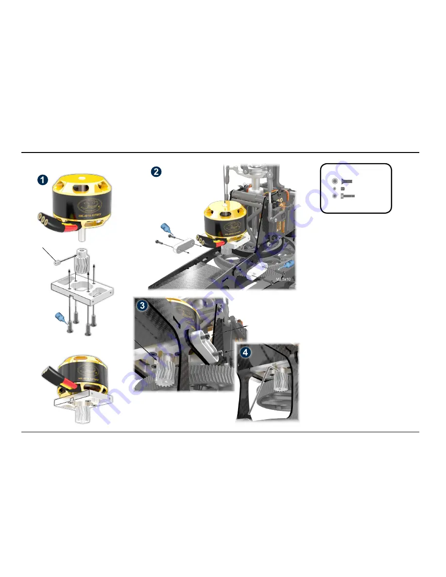
Installation of Motor and Gear Mesh
1) Mount the motor as shown in image (1), using the four
countersunk screws M3x10. Make sure that the M3x3 set
screw is placed at the flattened area of the motor shaft. Do
not fasten the set screw now (it can only be used once!)
- the pinion will be positioned later.
2) Mount the motor plate, as shown in (2), using the four
set screws M2.5x10 and the additional aluminum braces.
Do not tighten the screws completely, as the entire motor
plate should be still moveable.
3) Push the motor with pinion as close to the main gear as
possible, see image (3). The centers of the herringbone of
pinion and main gear must be aligned exactly. The main
gear has a slight axial play for easy adjustment.
4) Now fix the pinion to its final position by tightening the
M3x3 set screw. This set screw can only be used once.
You must secure it by using thread lock!
5) Pinion and main gear should have minimal gear mesh.
The main gear is not 100 % round (due to the free wheel
unit). Therefore there will be a small area without any
gear mesh. This is normal. Do not use paper for setting
the gear mesh (this does not work with the herringbone
gear!). Now secure the M2.5 socket head cap screw with
thread lock.
6) During pre-flight check, before each flight, the gear
backlash must be checked! Also, the gear must be che-
cked for wear and tear. If necessary, adjust the gear mesh
and/or replace the gears. Note that the motor ball bearing
can also be subject to wear and tear, as well as to excess
play.
Bag 6
Do not tighten yet!
Manual LOGO 480 - ©Mikado Model Helicopters GmbH -2013- Page 12
10 Motor Installation
Bag 6
M2,5x10
M3x10
M2,5x10

