background image

Manual 

LOGO 600 

- ©Mikado Model Helicopters GmbH - Page 6

5

4x 

 M3

4x 

 M3x10

4x 

 M3x3

1x 

4x 

 M3x8

1x 

 10x16x0,2

1x 

 10x16x0,5

1x 

 3x16

1x 

 M2,5x8

 

4

10x16x0,2

10x16x0,5

M3x8

(4x)

M3x10

M3x10

M3 Stopp (4)

M3x20

(7x)

1x 

 2,2x6

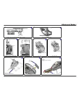
Secure scids using set screws 3x3.

Tighten tooth belt:
Pull tail rotor backwards and tighten screws

Grease

autorotation hub

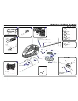
4 Main Gear & Tail Boom Assembly

Bag 2 • Bag 3 • Bag 6 • Bag 8

Bag 2

Swashplate bag 3

Bag 8

Tighten the pivot bolts 
very carefully. Do not 
overtighten them, as 
they will break off.

Attach the tail boom with a screw 2.2x6

Push in tail boom until locked.

Summary of Contents for Logo 600

Page 1: ...do heli de Mikado Model Helicopters GmbH 2010 V1 0 LOGO 600 Manual Mikado Model Helicopters GmbH Friedrich Klausing Straße 2 14469 Potsdam Germany phone 49 0 331 23749 0 fax 49 0 331 23749 11 www mikado heli de ...

Page 2: ...rs yards away from a spinning rotor blades Do not touch the motor immediately after use It may be hot enough to cause burns Perform all necessary maintenance PRIORTO ADJUSTING AND OPERATINGYOUR MO DEL OBSERVE THE FOLLOWING Warning Operate the helicopter only outdoors and out of people s reach as the main rotor operates at high rpm Warning While adjusting stand at least 10 meters yards away from th...

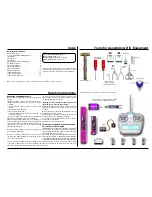
Page 3: ...12 2x M3x20 10x19x5 M2 5x16 4x 3x7x3 3x17 M2 5x12 M2 5x12 M3x10 M3x20 M3x10 Using the rod M2 5x60 from bag 7 position all 14 nylon nuts in the right side frame Before you combine the two sides of the main frame attach the two belt tensioners 4089 bag 6 1 Mainframe Bag 1 Bag 1 All parts shown in the boxes are displayed in real size ...

Page 4: ...3x35 4x M3x8 3 M3x16 4x8x2 6x8x0 5 M2 5x6 M3 Stopp 2 5x6x0 5 1x 3x5x5 1x M2x8 1x Kugel ball Rotule Ø4 8x2 1x 3x5x0 5 1x M3x14 2x 3x6x2 5 2x 6x8x0 5 2x M2 5x6 2x 2 5x6x0 5 2x 4x8x3 2x 4x8x2 2x M3x16 2x 4x8x3 5 2x M3 1 1 2 3 Ball Ø6 mm 2 Tail Rotor Bag 5 Bag 5 Bag 5 Apply grease to bearing Small inner diameter Large inner diameter Glue ball bearings using 5min Epoxi ...

Page 5: ... M2 5x30 4x Kugel ball Rotule Ø6x3 2x M3x40 M3x40 M2x6 M2 Stop M3x3 M2 5x30 2x Ø4x705 mm Ø5x520 mm 3 Tail Boom Bag 6 Bag 5 Bag 6 11 Bag 6 11 Ball Ø6 mm Ball Ø6 mm Attach the ball links so that the engraved number is on the outer surface pointing to wards you 5 Min Epoxy 5 Min Epoxy ...

Page 6: ...topp 4 M3x20 7x 1x 2 2x6 Secure scids using set screws 3x3 Tighten tooth belt Pull tail rotor backwards and tighten screws Grease autorotation hub 4 Main Gear Tail Boom Assembly Bag 2 Bag 3 Bag 6 Bag 8 Bag 2 Swashplate bag 3 Bag 8 Tighten the pivot bolts very carefully Do not overtighten them as they will break off Attach the tail boom with a screw 2 2x6 Push in tail boom until locked ...

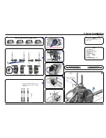
Page 7: ... Servo Installation Bag 1 Bag 9 Bag 9 Bag 1 Bag 9 Bag 1 Apply a small amount of oil to the rotor shaft If you are installing Futaba servos add the distance plate for the two aileron servos Aileron left Aileron right Elevator Rudder LOGO Rotor Head V Stabi flybarless head 16 mm 16 mm 16 mm 14 mm Attach the ball links so that the engraved number is on the outer surface pointing towards you ...

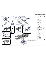
Page 8: ...0 M3x35 3x7x3 3x5x2 3x6x2 5 M3x14 M3x5 3x5x0 3 8x11x0 5 3x8 2x M5x12 M5x12 10x14x1 8x14x4 11 5x16x1 11 5x16x1 6 V Bar Rotor Head 600 Bag 7 Bag 7 Please adjust the swashplate driver in such a way that the balls on the inner and outer ring of the swashplate are positioned exactly on a line along the longitudinal axis of the heli Large inner diameter Small inner diameter Apply grease to bearing If th...

Page 9: ...is correctly aligned take the motor out of the mainframe and tighten the set screw Gear Backlash Move the motor with the pinion until it is limited by the gear Tighten one of the M4x14 screws slightly You must still be able to swivel the motor around its own axis In this way you can easily determine the correct distance between the main gear and the pinion There should be no gear backlash At the s...

Page 10: ...ry with the 3 Velcros Position of servo arms for the tail rotor when sticks are centered Position of servo arms for the aileron servos when sticks are centered 0 deg Pitch Velcro V Bar Main board Receiver Position for mounting V Bar gyro Position of LiPo battery for the power supply of receiver speed controller ...

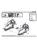
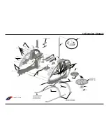
Page 11: ...Manual LOGO 600 Mikado Model Helicopters GmbH Page 11 LOGO 600 04366 10 Overview Chassis ...

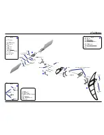
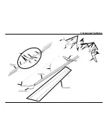
Page 12: ...Manual LOGO 600 Mikado Model Helicopters GmbH Page 12 11 Overview Tail Rotor ...

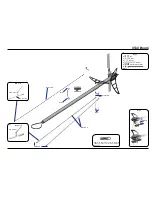
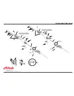
Page 13: ...Manual LOGO 600 Mikado Model Helicopters GmbH Page 13 Construction Rendering Mehran Mahinpour Tirooni Layout Realisation CDT Berlin www mikado heli de 12 Overview V Bar Head ...

Reviews: