background image

9

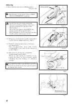
Fig.6

Idling position

Stop position

Throttle lever

Move the lever from Idling 

to Stop position.


5 Operation 


5-1 Move the throttle lever quickly from the IDLE to 

OPERATION position to start tamping action. DO 

NOT  move  the  throttle  lever  slowly  as  this  may 

cause damage to the clutch or spring.   


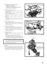
5-2  The  tamping  rammer  is  designed  to  tamp  the 

ground 650 to 700 times per minute for MT-76D at 

an engine speed of 3,100 rpm.   

Increasing  the  engine  speed  above  the 

recommended  rpm  will  not  increase  the  rammer 

effectiveness.   

Impact will actually decrease because a resonance 

is  created  rather  than  a  tamping  effect,  and 

damage to the unit can result.   


5-3 The rammer can be warmed by quickly moving the 

throttle lever from the OPERATION to the IDLE 

position several times until the rammer operates 

smoothly.   


5 -4 The tamping rammer is designed to travel forward 

while tamping.   

To increase travel speed, pull back slightly to the 

handle  so  that  the  rear  of  the  foot  contacts  soil 

first.   


5-5  To  stop  tamping,  quickly  move  the  throttle  lever 

from the OPERATION to IDLE position.   

Do  not  move  the  lever  slowly  as  irregular  action 

and damage may result.   


6. Stopping the Engine   


6-1 Move throttle lever quickly from idle to STOP while 

pressing the throttle lever button.   

Run the engine for three minutes at idle speed to 

allow for proper cool down.   

Following above procedure will prevent improper 

cylinder  lubrication  caused  by  overheated 

engine.(Fig.6) 

Summary of Contents for MT-76D

Page 1: ...UCTION MANUAL We thank you for selecting Mikasa Tamping Rammer For your safe and proper operation please read this manual and be always sure to keep it ready for reference Contents of Declaration of C...

Page 2: ......

Page 3: ...al number please refer it on front page 12 Conformity assessment according to Annex VIII Full Quality Assurance procedure 13 Name and address of the Notified Body Soci t Nationale de Certification et...

Page 4: ...n l annexe VIII procedura Garanzia di Qualit totale 13 Nom et adresse de l organisme notifi 14 Mandataire dans la Communaute Europeenne 15 Directive concernee Est egalement conforme aux dispositions d...

Page 5: ...remature machine wear due to uneven loads on the machine Use the machine with confidence for tamping earth and sand soil sand gravel and asphalt Do not use the machine for other type of jobs The upper...

Page 6: ...f you do not feel well due to overwork or illness If you are taking any medicine If you are under the influence of alcohol For details about the engine refer the separate instruction manual for the en...

Page 7: ...ing operation while moving it or stopping operation stop work immediately Before leaving the machine be sure to turn the engine off Also make sure to turn the engine off if you want to move the machin...

Page 8: ...ength to support the machine DO NOT lift it higher than necessary for safety DO NOTuse a damaged wire cable Never lift or lower the machine rapidly when using a hydraulic shovel or a crane When liftin...

Page 9: ...o oil or fuel leaks If fuel is leaking drain it all from the fuel tank Appropriate maintenance of the machine is required to ensure safety and keep the machine performing well Always be aware of the m...

Page 10: ...Fuel Starting system Recoil starter with Auto return decompression device Jumping stroke 50 80 mm WARNING The engine exhaust from this product con tains chemicals known to the State of Califor nia to...

Page 11: ...e power takes place by increasing engine speed to engage a centrifugal clutch Circular motion is converted into vertical motion to create impact force 3 Prior to Operation 3 1 Identification of Contro...

Page 12: ...to release decompression The decompression lever will return automatically when the recoil starter is pulled Fig 5 4 4 Return the recoil starter and pull the handle sharply and quickly Warm up the eng...

Page 13: ...amage to the unit can result 5 3 The rammer can be warmed by quickly moving the throttle lever from the OPERATION to the IDLE position several times until the rammer operates smoothly 5 4 The tamping...

Page 14: ...m the engine and control area Clean or replace air cleaner as necessary Check and retighten all fasteners as necessary Check spring box and bellows for oil leaks Repair as needed Remove element from p...

Page 15: ...nkcase body side Wash the element outside in detergent solution Shake out excess moisture and dry the element Clean inside element with air from the inside of element 7 6 Cleaning the Oil Filter Drain...

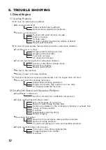
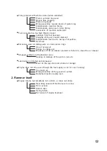
Page 16: ...el pipe Does not reach the starting revolution Governor fork and sleeve mating surface problems Governor spring problems Fly plate and sliding part wear and operation problems Revolution fluctuation V...

Page 17: ...from fuel passage Clogging of the air cleaner element Inappropriate fuel due to mixing of impurities Overload Fuel consumption too high black smoke Use of wrong oil Failure to change oil Breakage of t...

Page 18: ...Note...

Page 19: ......

Page 20: ...PRINTED IN JAPAN MIKASA SANGYO CO LTD 1 4 3 Sarugakucho Chiyoda ku Tokyo 101 0064 Japan...

Reviews: