5-1.
5-2.
5-3.
5-4.
5-5.
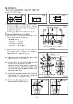
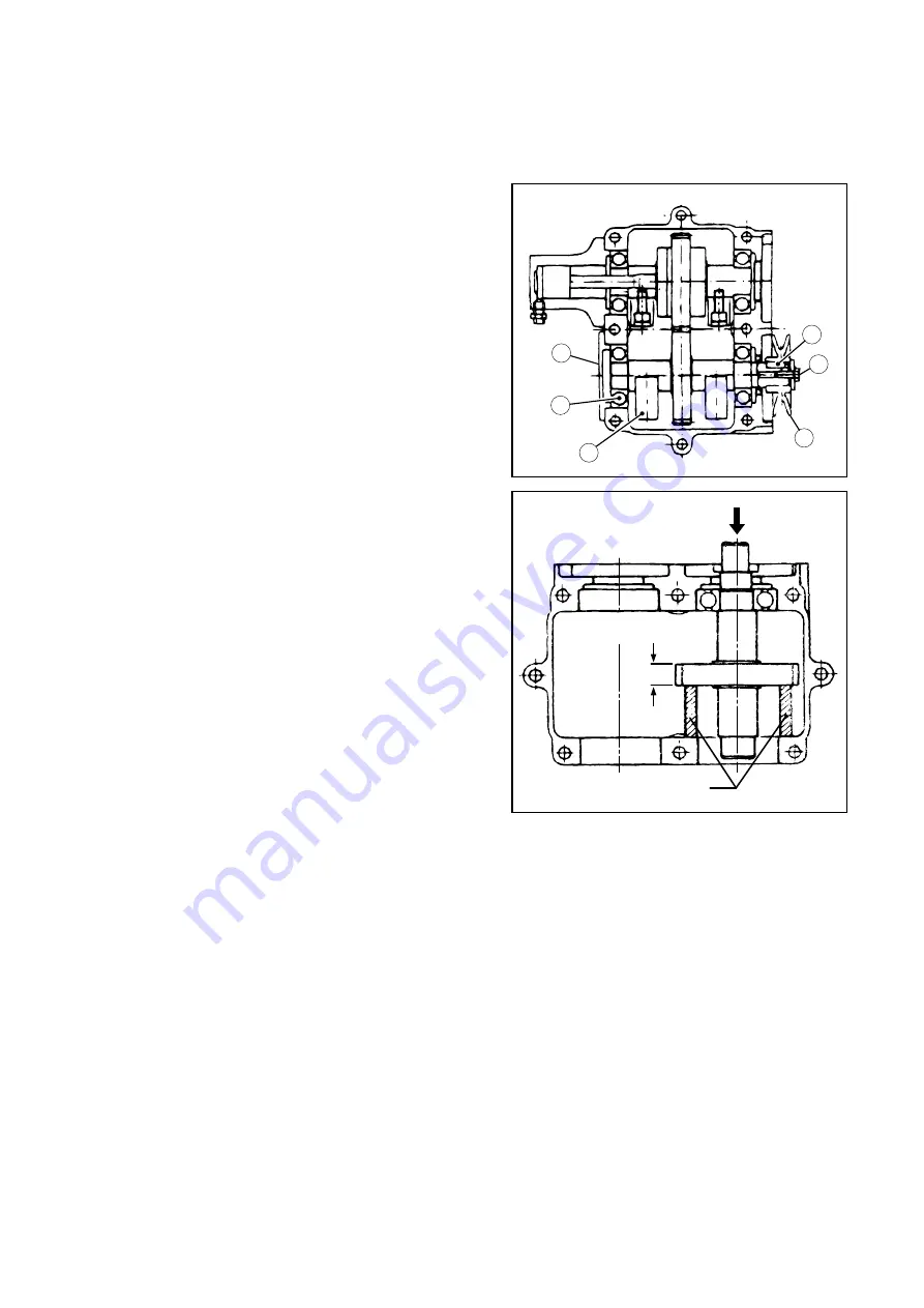
With its mounting bolt(38) removed, pull out the
pendulum pully(35) from drive shaft. Have the key(6)
removed as well(See Fig.12).
With its four mounting bolts removed,remove the
bearing cover(21)(See Fig.12).
With its four mounting bolts removed, remove pendu-
lum (18) and push out the drive shaft assembly to
the bearing cover side before removing the
bearing(See Fig.12).
As shown in Fig.13,remove upper stop ring(5) and
engage supports between the drive gear (30) and
inner surface of vibrator case. Press the drive shaft
from top and remove drive gear within the vibrator
case. The gear having been pressed-in over the
distance of about 2cm, its removal will be easy
beyond that point.
Pull out the drive shaft from vibrator case.
<Common to MVH-R60, 100 (120) AND 150>
*
MVH-100(120) is used as an example here.
Disassembling teh driving shaft side:
Fig.13
Press
Remove upper
contraction stop ring
2cm
Support
2
6
21
18
35
38
Fig.12
13


