●
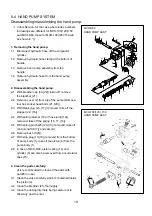
●
●
1.
2.
2-1.
2-2.
2-3.
2-4.
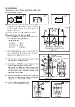
Vibrator case is to be supported by means of Jig B
with its belt side coming to bottom.
Have the key 10x8x19(6) and upper (opposite to belt
side) stop ring(5) engaged to drive shaft.
After piacing such assembly inside the vibrator case,
have the drive gear(7) (with its punched side coming
to top) and stop ring(5) engaged to halfway of the
drive shaft, in such order.
With the Jig A arranged as shown in Fig.15, push the
drive gear into drive shaft by means of press and
engage the lower stop ring(See Fig.16).
Press the bearing of opposite to belt
side(2) into drive shaft(See Fig.17).
Jigs to be used (3 types)
Before proceeding with reassembly, remove liquid
packing thoroughly from mating surface of vibrator
case and compaction plate. Clean and de-grease all
the other parts as well.
Coat the press-fit area with molybdenum grease.
Have both of the two bearings(2) inserted in the belt
side of vibrator case(1) (See Fig.14).
Bearings in use:
MVH-R60: 6206C4
MVH-100(120): 6307C4
MVH-150: NJ307MC4
Within the vibrator case, press the drive gear(7) into
drive shaft(3) with its punched side coming to
top(Opposite to belt side) (See Fig.15).
REASSEMBLY
<Common to MVH-R60, 100 (120) AND 150>
Jig A
Jig B
Jig C
50
6
Φ
70
80
80
10
30
5
Φ
45
55
Re-assembling the driving shaft:
Fig.14
Driven shaft side
Drive shaft side
Belt side
Coat with
molybdenum grease.
Opposite to belt side
Fig.15
Top
Bottom
Jig A
Jig B
Press-in
Punched surface
on opposite
to belt side
Drive side
Coat with
molybdenum grease.
7
6
5
5
3
1
Drive side
Drive side
2
2
5
5
Fig.16
Fig.17
14


