1.
2.
3.
4.
4-1.
4-2.
4-3.
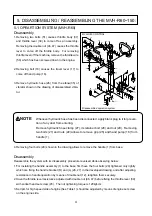
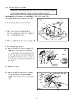
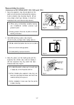
Remove any hydraulic hose connection.
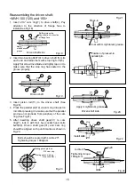
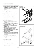
With vibrator case mounting bolts(46,47)
removed, separator the vibrator case assembly
from vibrating plate(See Fig.1)
With four bolts(30) removed, remove cylinder(29).
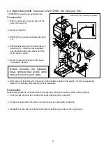
Disassembling the piston:
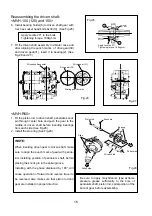
With the vibrator case inverted upside down,
rotate gear in either direction to cause the
piston assembly(15) to be projected from the
vibrator case, before removing the expansion
stop ring(17) from inside of the piston.(Use a
bent nose type stop ring plier for this purpose.)
(See Fig.2)
Withdraw the piston.
With the contraction stop ring(14) removed,
take off bearing(13) and expansion stop
ring(17) which had been removed earlier(See
Fig.3).
5-3
VIBRATION SYSTEM
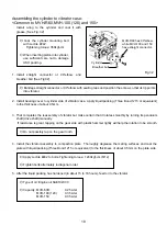
During disassembly and reassembly work, use care not damage any parts.
O-ring, oil seal, packing or the like must be relaced with new one.
Disassembly
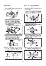
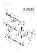
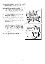
<Common to MVH-R60, 100 (120) and 150>
*
MVH-R60 is used as an example hereunder.
Fig.1
Fig.2
Fig.3
Piston
Piston
Gear
Expansion
stop ring
Expansion stop ring
Contraction stop ring
Cylinder
Bearing
9


