INDICATORS
Pre-fault alarm................................................................ Red indicator
Leakage trip delay time.................................................. Red indicator
Leakage trip.................................................................... 7-segment display and red indicators
Manual test trip............................................................... 7-segment display and red indicators
ZCT connection fault...................................................... 7-segment display and red indicators
Trip records.................................................................... 7-segment display
Real-time leakage current.............................................. 7-segment display
ZERO-PHASE CURRENT TRANSFORMERS
To operate with Mikro's ZCT series of current transformers
MECHANICAL
Mounting......................................................................... Standard 35mm DIN rail mounting
Approximate weight........................................................ 0.38kg (excluding ZCT)
9.
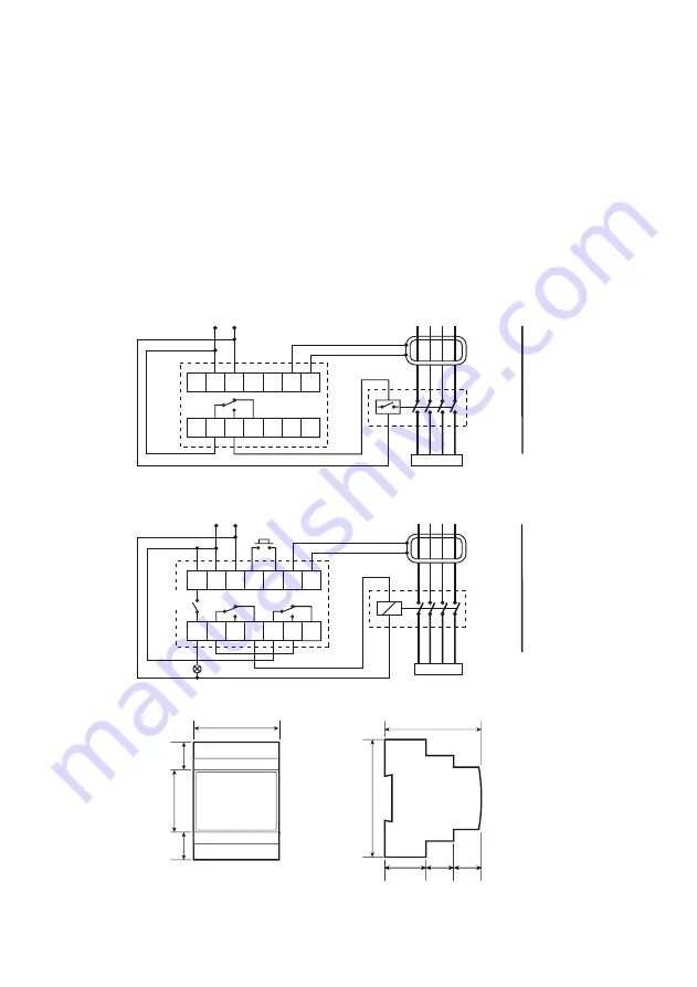
CONNECTION DIAGRAMS
10. CASE DIMENSION
* Applicable to DIN310E series only
TRIP
CONTACT
LOAD
L1 L2 L3 N PE
6
2
3
4
5
7
1
8
9
10
11
12
13
14
L
N
AUX
SHUNT
TRIP
MIKRO
ZCT
DIN310
TRIP CONTACT SAFETY CONTACT
LOAD
6
2
3
4
5
7
1
8
9
10
11
12
13
14
L
N
AUX
CONTACTOR
MIKRO
ZCT
DIN310E
REMOTE
RESET
Typical application diagram for DIN310 series
Typical application diagram for DIN310E series
ALARM
CONTACT
Front
Side
71 mm
20 mm
45 mm
20 mm
70 mm
85 mm
30 mm 20 mm 20 mm
The EARTH wire
must not pass
through the ZCT
The EARTH wire
must not pass
through the ZCT
L1 L2 L3 N PE


