[2]
Introduction
The scope of this manual
This user guide assumes that readers have a basic knowledge of the DMX512-A communication protocol. The data frame
structure and other specifics of the DMX512 protocol will not be discussed in this manual. Before working with the DMX
Click, it is strongly recommended that you familiarize yourself with the DMX512-A standard.
What is DMX Click?
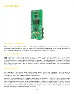
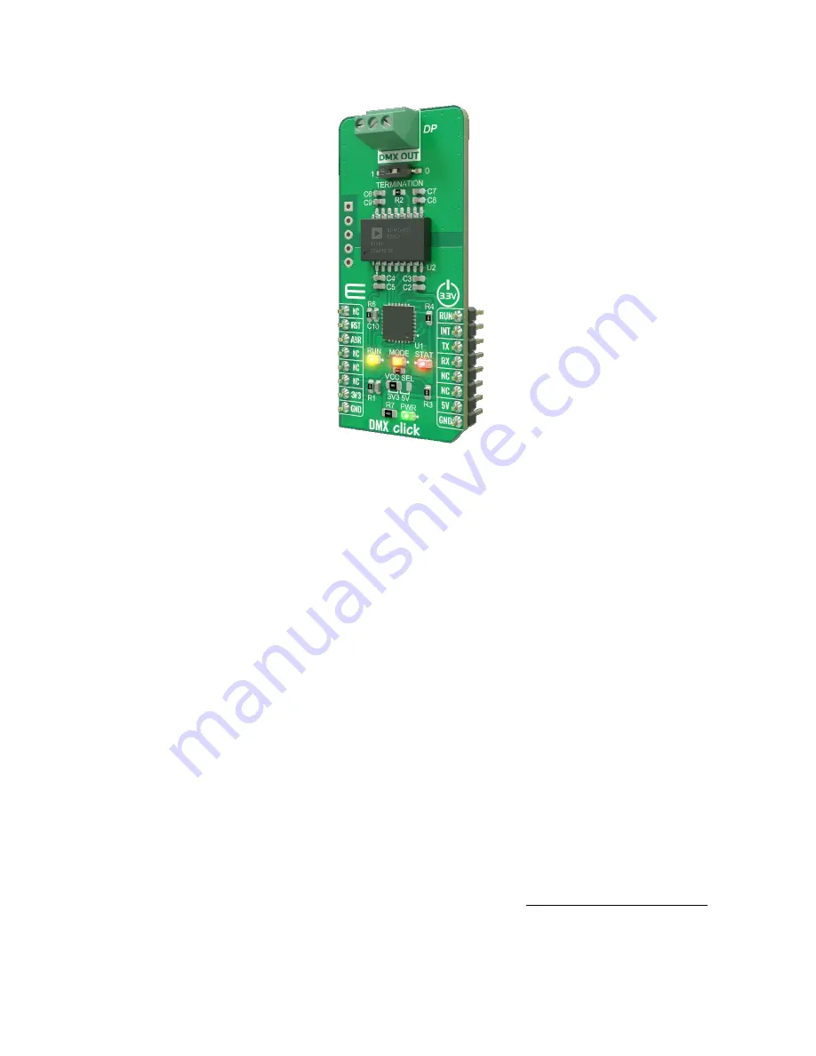
DMX Click
is designed to accept the UART data stream on the RX pin and packs it into DMX frames, generated at the
DMX output (3-pole screw terminal). Since the DMX 512-A protocol (DMX in the following text) is most commonly used
to control stage lighting and other stage equipment (e.g. fog machines), it is implemented on the top of the RS485 physical
layer which has a very good immunity to electromagnetic interference (EMI), which is typical in a noisy stage environment.
The Click board™ also provides galvanic isolation between the DMX bus and the host application, with no additional
components required.
Operating Modes
The Click board™ can be operated both as DMX MASTER and DMX SLAVE. When operated as a MASTER, it can be
used to control other SLAVE devices on the bus. It is capable of controlling a single DMX 512 universe (512 channels).
Note that there can be only a single MASTER device per DMX bus.
Each of the two MASTER and SLAVE operating modes has two sub-modes. The Click board™ can be actively relaying
incoming UART data to the DMX bus (RUN mode) or it can be waiting for the configuration commands (CFG mode).
More information about the operating modes and sub-modes can be found in the
Configuring the Click board™
section in
this manual. For now, it is enough to say that the data at the RX input is interpreted differently depending on the currently
selected sub-mode. Also, unlike MASTER and SLAVE operating modes that can be set only once per reset cycle, these
sub-modes can be freely selected during normal operation.


