E a s y M x
P R O
v 7 a
U s e r M a n u a l
P A G E 29
TFT display
320x240 pixels
TOUCH PANEL
CONTROLLER
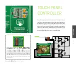
Touch panel is a glass panel whose surface is covered with two layers of
resistive material. When the screen is pressed, the outer layer is pushed
onto the inner layer and appropriate controllers can measure that pressure
and pinpoint its location. This is how touch panels can be used as an input
devices. EasyMx PRO v7a is equipped with touch panel controller and
connector for 4-wire resistive touch panels. It can very accurately register
pressure at a specific point, representing the touch coordinates in the
form of analog voltages, which can then be easily converted to X and Y
values. Touch panel comes as a part of TFT 320x240 display.
Enabling Touch panel
CN29
PM
R
D
PM
W
R
G
N
D
VC
C
N
C
R
S
N
C
D
1
D
2
D
3
D
4
D
5
D
6
D
7
C
S
D
0
R
ST
N
C
+
5V
B
PW
M
1
20
XR
YU
XL
YD
21
24
GLCD-TFT SOCKET
Q3
BC856
Q4
BC846
R61
10K
R59
1K
VREF
R65
10K
R63
4K7
VCC-3.3V
Q6
BC856
VREF
R67
10K
Q7
BC846
R71
10K
C35
10nF
R70
100K
Q8
BC846
R78
10K
C40
10nF
R77
100K
R75
4K7
VCC-3.3V
RIGHT
TOP
DRIVEA
DRIVEB
E14
10uF
VCC-3.3V
FP4
FERRITE
E15
10uF
VCC-1.8V
VREF
LEFT
BOTTOM
PB8
PB9
1
2
3
4
5
6
7
8
O
N
SW11
DRIVEA
DRIVEB
LEFT
BOTTOM
PB0
PB1
DATA BUS
RIGHT
TOP
LEFT
BOTTOM
Touch panel is enabled using
SW11.5
,
SW11.6
,
SW11.7
and
SW11.8
switches. They connect
BOTTOM
and
LEFT
lines of the touch panel with
PB0
and
PB1
analog inputs,
and
DRIVEA
and
DRIVEB
with
PB8
and
PB9
digital outputs
on microcontroller sockets. Prior to using Touch panel in
your application, make sure to disconnect other peripherals,
LEDs and additional pull-up or pull-down resistors from the
interface lines that could interfere with signals and cause
data corruption.
MUL
TIMEDIA

