E a s y P I C P R O v 8 M a n u a l
P A G E 7
O V E R V I E W
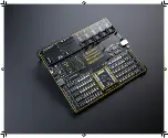
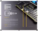
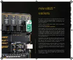
EasyPIC PRO v8 offers
five improved mikroBUS
™
sockets,
allowing interfacing with
a vast amount of electronic circuits and reference designs, standardized under
the Click board trademark. Click boards
™
are simple to use, require no additional
hardware configuration and can be easily connected to the development board
by inserting them into any of the available mikroBUS
™
sockets. A new design of
the mikroBUS
™
socket allows even easier interfacing with the Click board
™
line of
products: it has a sturdier design which helps aligning the Click board
™
correctly.
To read more about development improvements and huge benefits offered by the
mikroBUS
™
and Click board
™
line of products, visit the official Mikroe web page at
www.mikroe.com
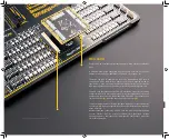
EasyPIC PRO v8 development board is equipped with
two display connectors
,
located in the middle section of the board. One connector is a single row 16-pin
header which supports 2x16 characters Liquid Crystal Display (LCD) in 4-bit mode,
offering an optional PWM backlight driving feature. The second display connector
is a standardized 2x20-pin female socket, which supports a vast number of display
boards, featuring different display modules, such as
TFT Board line of products
.
TFT Board displays come in different sizes, they support various resolutions, and
they feature different capabilities. All these display boards can be easily mounted to
the existing connector offering complete freedom of choice. For more information,
please visit the official Mikroe web page at
www.mikroe.com
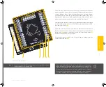
The
I/O (Input/Output) section
occupies the lower part of the development board
and contains available MCU pins routed to 2x5-pin headers for easy access. All of
them are equipped with configurable pull-up or pull-down resistors, buttons for
applying logic states to MCU pins, and LED indicators. Pins are divided into groups
following the grouping concept used on the MCU itself. This section is where the
most interaction with the MCU takes place.
Communication
options such as
USB-UART, USB DEVICE
and
Ethernet
, are also
included. The respective USB, USB-UART, and Ethernet connectors are positioned
at the edges of the development board, so they can be easily accessed. This is also
true for the power connectors, as well as for the external programmer/debugger
connector. This allows clean and clutter-free cable management.
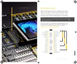
EasyPIC PRO v8 development board is supported by a powerful
CODEGRIP Suite,
offering complete control over the EasyPIC PRO v8 development board
. It is
used to intelligently manage programming and debugging tasks, and to configure
various other options and settings, providing visual feedback through its clean and
comprehensive Graphical User Interface (GUI). To better understand how to operate
and configure EasyPIC PRO v8 development board and its integrated CODEGRIP
module, a separate manual is provided at
www.mikroe.com/manual/codegrip
Summary of Contents for EasyPIC PRO v8
Page 5: ...E a s y P I C P R O v 8 M a n u a l P A G E 5...
Page 26: ...The 8th generation of hardware perfection...
Page 27: ......
Page 29: ......

