E a s y P I C v 8 f o r P I C 2 4 / d s P I C 3 3
M a n u a l
P A G E 19
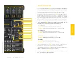
Crystal oscillator
Most of PIC MCU devices can use an external quartz-crystal oscillator. There are two
sockets for installing the crystal oscillator, depending on which MCU socket will be
used:
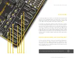
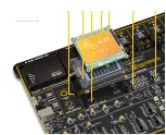
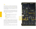
Crystal oscillator socket OSC1(X1)
is routed to DIP20A, DIP20B, DIP18 and DIP14
MCU sockets
(3)
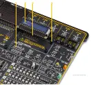
Crystal oscillator socket OSC2(X2)
is routed to DIP28A, DIP28B and DIP28C MCU
sockets
(4)
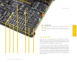
Above the DIP20A MCU socket, there is a jumper J16
(5)
used to specify whether the
OSC1/RA2 and OSC1/RA3 will be used as GPIO on the corresponding MCU sockets, or
connected to the OSC1 crystal oscillator socket:
J16 (OSC1)
UP position:
allows the RA2 and RA3 to be used as GPIO lines
DOWN position:
connects the RA2 and RA3 to the crystal oscillator socket OSC1
Above the DIP28A MCU socket, there is a jumper J14
(6)
used to specify whether the
OSC2/RB1 and OSC2/RB2 will be used as GPIO on the corresponding MCU sockets, or
connected to the OSC2 crystal oscillator socket:
J14 (OSC2)
UP position:
allows the RB1 and RB2 to be used as GPIO lines
DOWN position:
connects the RB1 and RB2 to the crystal oscillator socket OSC2
Above the DIP28C MCU socket, there is a jumper J15
(7)
used to specify whether the
OSC2/RA2 and OSC2/RA3 will be used as GPIOs on the corresponding MCU sockets, or
connected to the OSC2 crystal oscillator socket:
J15 (OSC2)
UP position:
allows the RA2 and RA3 to be used as GPIO lines
DOWN position:
connects the RA2 and RA3 to the crystal oscillator socket OSC2
C O N N E C T I V I T Y


