P A G E 26
E a s y P I C v 8 f o r P I C 2 4 / d s P I C 3 3
M a n u a l
mikroBUS
™
sockets
The superior connectivity features of the EasyPIC v8 for PIC24/dsPIC33 development
board are rounded up with five standardized mikroBUS
™
host connectors
(1)
. It is a
considerable upgrade for the board, as it allows interfacing with the vast amount of
Click boards
™
.
mikroBUS
™
is the add-on board standard that offers maximum expandability with the
smallest number of pins. More information at
www.mikroe.com/mikrobus
All the mikroBUS
™
sockets are now redesigned and improved. They became much
sturdier, allowing a better grip of the Click board
™
. In addition to added horizontal
supports between two 8-pin connectors, the right lower edge is chamfered at the
angle of 45°, the same as the Click board
™
, making it seamlessly fit into the mikroBUS
™
socket. The new mikroBUS
™
socket is now a fully-fledged, standardized monolithic
component with all its pins clearly labeled, offering very good grip for the Click board
™
,
preventing it to flip over or to be placed incorrectly.
The mikroBUS
™
socket supports the following communication interfaces: SPI, UART,
and I2C. There are also single pins reserved for PWM, Interrupt, Analog input, Reset,
and SPI Chip Select. The mikroBUS
™
socket also contains pins with the two power rails
(3.3V and 5V), along with the GND pins.
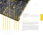
Each MCU socket has the appropriate pins routed to the mikroBUS
™
sockets.
Therefore, each mikroBUS
™
socket pin is clearly labeled on the development board.
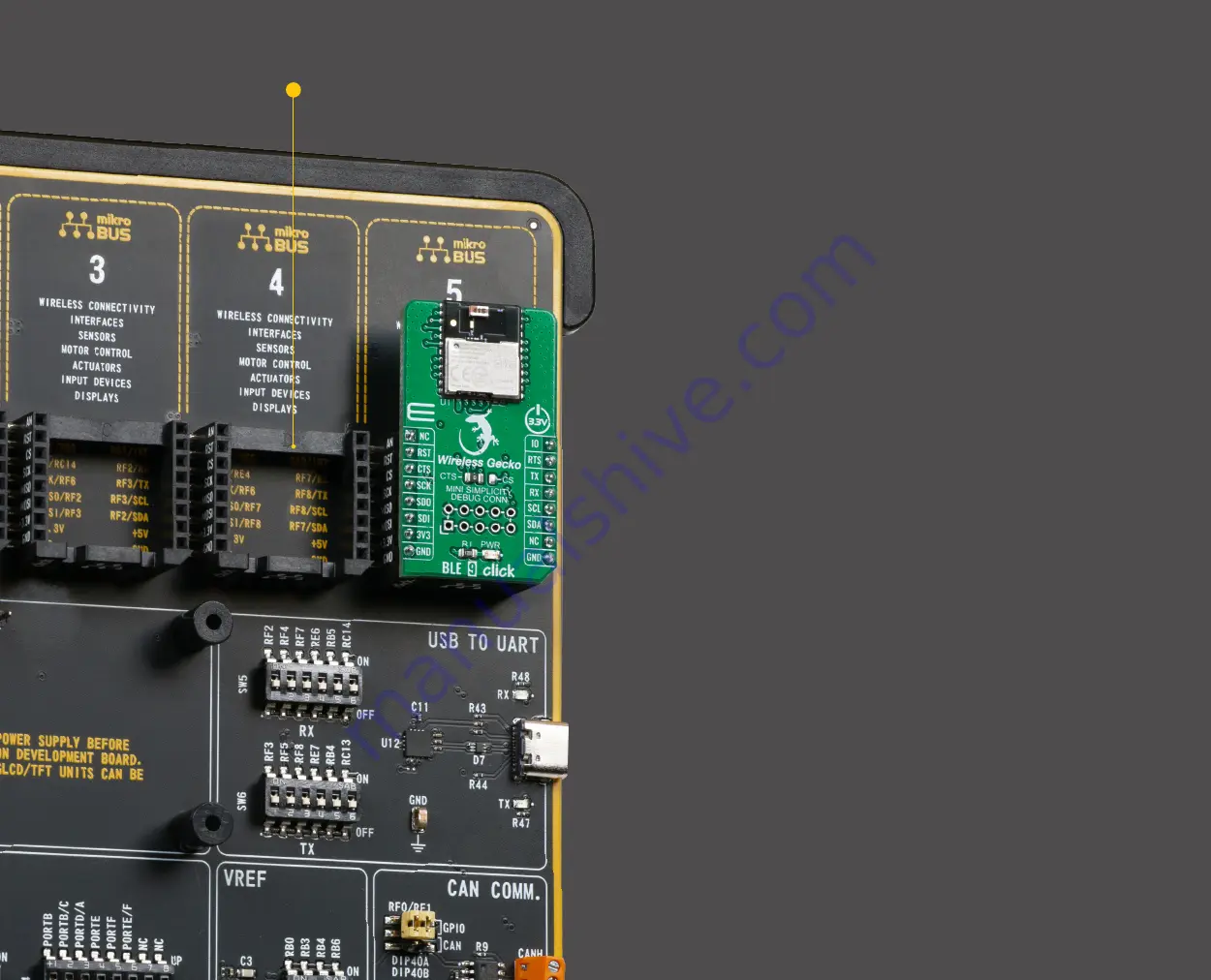
This helps users to identify to which MCU pin its routed to. Also, each mikroBUS
™
socket is labeled on the development board with its ordinal number, by which the
connector is referenced to in the Mikroe development environment, software
applications, tutorials, etc.
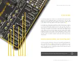
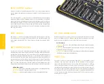
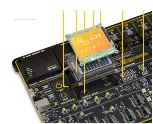
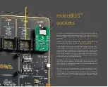
Figure 12: Main board with
mikroBUS™ sock
et close up view
1


