E a s y P I C v 8 f o r P I C 2 4 / d s P I C 3 3
M a n u a l
P A G E 31
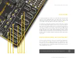
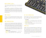
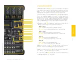
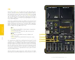
and accompanying circuitry. Therefore, the development board offers two jumpers
located in the USB section, allowing to specify whether these pins should be used for
other purposes (i.e. as GPIO lines) or they should be used as USB lines:
J8
(3)
GPIO (up):
allows the RB12 and RB6 pins to be used for other purposes
USB (down):
connects the RB12 and RB6 pins to the USB-C conn. and
accompanying circuitry
J9
(4)
GPIO (up):
allows the RB10 and RB11 pins to be used for other purposes
USB (down):
connects the RB10 and RB11 pins to the USB-C conn. and
accompanying circuitry
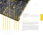
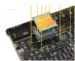
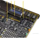
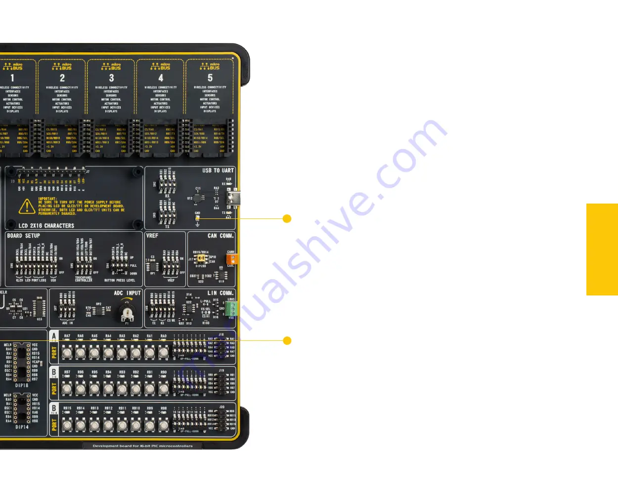
Figure 15: Main board partial left side view
COMMUNICA
TION
Additional GNDs
The EasyPIC v8 for PIC24/dsPIC33 development board contains exposed GND
(5)
pins
which can be used to connect measurement or testing equipment. These additional
GND pins allow secure connection with the instrumentation probes, avoiding loose
cables or unreliable contacts that might compromise the accuracy of the readings.
5
5

