background image

Page 6


VCC-3.3

VOUT-3.3 VOUT-3.3

VOUT-3.3

IO14
IO12
IO13
IO15

IO2

ESP_RST

ESP_TXD
ESP_RXD

C3

10µF

VCC-3.3

VOUT-3.3

ESP_EN

LD1

PWR

18

18

17

17

16

16

15

15

14

14

13

13

12

12

11

11

10

10

9

8

7

6

5

4

3

2

1

GND

IO0

IO2

IO15

IO13

IO12

IO14

EN

3.3V

IO4

RXD

TXD

GND

IO5

RST

TOUT

IO16

GND

ESP-WROOM-02

U2

JT

A

G

_T

C

LK

JT

A

G

_T

D

I

JT

A

G

_T

D

O

JT

A

G

_T

M

S

MCU_RST

MCU_RST

U

A

R

T0

_R

TS

U

A

R

T0

_C

TS

U

A

R

T0

_R

X

U

A

R

T0

_T

X

ES

P_

TX

D

ES

P_

R

XD

ESP_RST

ESP_EN

UART0_TX

UART0_RX

UART0_CTS

JTAG_TMS

JTAG_TCLK

JTAG_TDO

JTAG_TDI

VOUT-3.3

VOUT-3.3

MCU_RST

R6

10k

R7

10k

R8

10k

R9

10k

R14

10k

R15

10k

C4

0.10µF

C2

0.10µF

UART0_RTS

Y2

32.768kHz

C8

12pF

C9

12pF

LD3

STAT

ST

A

TU

S_

LE

D

LD4

CONN

CONN_LED

C

O

N

N

_L

ED

R1

1k

R3

1k

1

2

3

4

5

6

7

8

9

10

J1

VCC-5V

VCC-5V

STATUS_LED

IO0

IO

0

R13

10k

IO

15

IO

13

R4

1k

C

3

D11

E11

F11

E1 D

1

D

2

C

1

C

2

B

1

A

9

A

10

A

1

B

2

A

2

A

3

B

3

D

3

D

4

A

4

B

4

C

4

A

6

A

5

B

5

D

5

B

6

C

5

C

6

D

6

A

7

A8

D

7

C

7

B

7

L2

L1

K2

K1

E2

E7

F7

A11

C11

K10

L10

H2

H1

L6

G7

E6

F3

G4

H7

K3

H4

E4

E3

F4

L11

K11

L7

B11

G2

G1

F2

F1

J2

J1

H10

MK64FN1M0VDC12

J11

H11

G11

G10

G9

G8

E10

D10

C10

B10

E9

D9

C9

F10

F9

F8

E8

B9

D8

C8

A

D

C

0_

SE

16

/C

M

P1

_I

N

2/

A

D

C

0_

SE

21

A

D

C

1_

SE

16

/C

M

P2

_I

N

2/

A

D

C

0_

SE

22

NC

NC

PTE0

PTE1/LLWU_P0

PT

A

4/

LL

W

U

_P

3

D

A

C

0_

O

U

T/

C

M

P1

_I

N

3/

A

D

C

0_

SE

23

V

R

EF

_O

U

T/

C

M

P1

_I

N

5

C

M

P0

_I

N

5/

A

D

C

1_

SE

18

PT

A

0

PT

A

1

PT

A

2

PT

A

3

D

A

C

1_

O

U

T/

C

M

P0

_I

N

4

C

M

P2

_I

N

3/

A

D

C

1_

SE

23

XT

A

L3

2

PTB17

PTB16

PTB11

PTB19

PTB10

PTB9

PTB1

LLWU_P5/PTB0

NC

PTB13

PTC0

PTB23

PTB22

PTB21

PTB20

PTB18

VSS

ADC0_DM0/ADC1_DM3

ADC0_DP1

VREGIN

VOUT33

USB0_DM

USB0_DP

VSS

PT

A

15

PTE5

VDD

PTE3

V

R

EF

H

LLWU_P6/PTC1

PTC2

RTC_WAKEUP_B

PTB12

ADC0_DP0/ADC1_DP3

ADC1_DM1

ADC1_DP1

ADC0_DM1

PT

E2

4

PT

E2

5

PT

A

16

PT

A

10

EX

TA

L3

2

V

BA

T

PT

A

5

V

R

EF

L

V

D

D

A

V

D

D

PT

A

11

PTB3

VSS

VDD

PTE6

V

SS

A

V

SS

PT

A

14

PTB2

ADC1_DM0/ADC0_DM3

ADC1_DP0/ADC0_DP3

PTE4/LLWU_P2

PTE2/LLWU_P1

PT

A

12

PT

A

13

/L

LW

U

_P

4

VSS

PTA17

VDD

PTA18

PTA19

RESET_b

PTA29

LLWU_P7/PTC3

LL

W

U

_P

9/

PT

C

5

PT

C

7

LL

W

U

_P

10

/P

TC

6

LLWU_P8/PTC4

LL

W

U

_P

14

/P

TD

4

PT

D

3

PT

D

1

LL

W

U

_P

14

/P

TD

6

LL

W

U

_P

12

/P

TD

0

PT

C

19

PT

C

16

PT

C

15

PT

D

11

PT

D

10

PT

D

9

PT

D

8

PT

D

7

PT

D

5

PT

D

12

PT

D

13

PT

C

18

PT

C

17

PT

C

10

PT

C

8

PT

C

9

LL

W

U

_P

11

/P

TC

11

PT

C

12

PT

C

13

PT

C

14

PT

D

14

PTB6

LL

W

U

_P

13

/P

TD

2

PTB8

PTB7

PT

D

15

B8

PT

E2

6

J1

0

L9

K

9

L8

K

4

L5 K

6

F6

G

6

J9

G

3

J7

H

8

J6

H

6

J5

H

5

J3 H3 L3 K5

L4

F5 G

5

E5

K

7

J8

H

9

K

8

J4

U1

MK64FN1M0VDC12

C5

2.2

µ

F

R5

10k

VOUT-3.3

C1

2.2

µ

F

VCC-5V

AN

RST

CS

SCK

MOSI

MISO

+3.3V

GND

PWM

INT

RX

TX

SCL

SDA

+5V

GND

MIKROBUS DEVICE CONN

VOUT-3.3

VCC-5V

1

2

3

4

5

ID

D+

D-

VBUS

GND

6

CN1

TVS1 TVS2

R11

27

R12

27

R10

1M

LD2

USB

VCC-3.3

VCC-USB

VCC-USB

R2

1k

GP0

GP1

GP0

GP1

D1

PMEG3010ER,115

D2

PMEG3010ER,115

Y1

12MHz

C6

12pF

C7

12pF

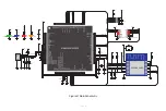
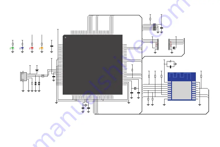
Figure 3: Main Schematic 

Summary of Contents for G2C click

Page 1: ...U S E R M A N U A L Go to Cloud G2C click The WiFi IoT gateway Click board which connects your IoT devices with the Click Cloud service provided by MikroElektronika Simple and reliable...

Page 2: ...being interested in our products and for having confidence in MikroElektronika The primary aim of our company is to design and produce high quality electronic products and to constantly improve the pe...

Page 3: ...able of Contents Introduction to Go to Cloud G2C click 4 mikroBUS pins 7 Onboard indicators and LED indicators 8 Pins description 8 UART interface configuration 9 Boot up sequence 10 Firmware update 1...

Page 4: ...ponents it requires makes the ESP WROOM 02 module an ideal solution for using it on the Go to Cloud G2C click The ESP WROOM 02 module uses the UART communication interface and it can be controlled by...

Page 5: ...WROOM 02 Finally there is a micro USB connector which is used to update the firmware of the Go to Cloud G2C click The firmware update is simple error proof and straight forward More information about...

Page 6: ...AC0_OUT CMP1_IN3 ADC0_SE23 VREF_OUT CMP1_IN5 CMP0_IN5 ADC1_SE18 PTA0 PTA1 PTA2 PTA3 DAC1_OUT CMP0_IN4 CMP2_IN3 ADC1_SE23 XTAL32 PTB17 PTB16 PTB11 PTB19 PTB10 PTB9 PTB1 LLWU_P5 PTB0 NC PTB13 PTC0 PTB23...

Page 7: ...ace in the form of 2x5 pin header is used only during the production phase for the upload of the initial firmware and it should not be used by the user as it may lead to malfunction of the Go to Cloud...

Page 8: ...operation Pins description RST Hardware reset INPUT This pin is used to reset the MCU This pin is internally pulled up to a HIGH logic level Driving this pin to a LOW logic level for 50 ms a reset fun...

Page 9: ...e the five second bootloader timeout will be completely skipped allowing for a faster start of the Go to Cloud G2C click More information about the secondary function of this pin is provided in the Bo...

Page 10: ...aracters should not exceed 5 seconds The timing interval greater than 5 seconds is considered as the EOL for any AT command end of line and the received command will be parsed as such Moreinformationa...

Page 11: ...event leading to a five second startup delay To skip the bootloader mode completely and boot up directly into the normal mode the CTS pin can be set to a HIGH logic level after the restart for at leas...

Page 12: ...ease use the provided micro USB connector CN1 with the HID bootloader application and a proper firmware file The JTAG 2x5 pin header J1 is not to be used for uploading the update since it can destroy...

Page 13: ...USB cable and connect it again initiating another five seconds interval After the MCU of the Go to Cloud G2C click is detected as on the picture above an appropriate HEX file with a proper firmware ve...

Page 14: ...damages MikroElektronika reserves the right to change information contained in this manual at any time without prior notice if necessary HIGH RISK ACTIVITIES The products of MikroElektronika are not...

Page 15: ...f you are experiencing some problems with any of our products or just need additional information please place your ticket at www mikroe com support If you have any questions comments or business prop...

Reviews: