background image

12

BIGdsPIC6 Development System 

MikroElektronika

page

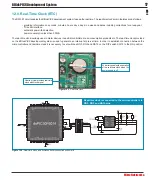
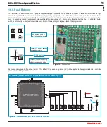
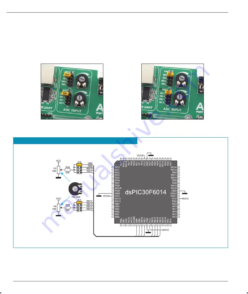
6.0. A/D Converter Test Inputs

An A/D converter is used for converting an analog voltage into the appropriate digital value. The A/D converter is linear, which means 
that converted number is linearly dependent on the input voltage value. The A/D converter built into the microcontroller converts an 
analog voltage value into a 10-bit number. Potentiometers P3 and P4 enable voltage to vary between 0 and 5V. The microcontroller 
with a built-in A/D converter is supplied with this voltage via test inputs. Jumpers J16 and J17 are used for selecting one of the 
following pins RB8 - RB15 to be supplied with A/D conversion voltage. Resistors R28 and R29 have a protective function and are used 

WROLPLWFXUUHQWÀRZWKURXJKWKHSRWHQWLRPHWHURUWKHPLFURFRQWUROOHUSLQ
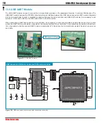
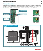
)LJXUH

: ADC (jumpers in default position)
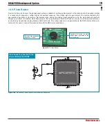
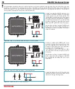
)LJXUH

: Pins RB8 and RB12 used as 

input pins for A/D conversion
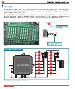
)LJXUH

: A/D converter test inputs and microcontroller connection schematic

127(

In order to enable the microcontroller to accurately perform A/D conversion, it is necessary to turn off LEDs and  pull-up/
pull-down resistors on the port pins used by the A/D converter.  

$'FRQYHUVLRQLVSHUIRUPHGYLD5%DQG5%PLFURFRQWUROOHUSLQV


Summary of Contents for BIGdsPIC6

Page 1: ...osen components and the use of machines of the last generation for mounting and testing thereof are the best guarantee of high reliability of our devices Due to simple design a large number of add on modules and ready to use examples all our users regardless of their experience have the possibility to develop WKHLU SURMHFW LQ D IDVW DQG HI FLHQW ZD Development System ...

Page 2: ...ce high quality electronic products and to constantly improve the performance thereof in order to better suit your needs The Microchip name and logo the Microchip logo Accuron dsPIC KeeLoq microID MPLAB PIC PICmicro PICSTART PRO MATE PowerSmart rfPIC and SmartShunt are registered trademarks of Microchip Technology Incorporated in the U S A and other countries Nebojsa Matic General Manager ...

Page 3: ...Programmer 9 4 0 ICD Connector 10 5 0 Power Supply 11 6 0 A D Converter Test Inputs 12 7 0 Voltage Reference Source 13 8 0 Serial EEPROM Module 13 9 0 MMC SD Connector 14 10 0 RS 232 Communication Module 15 11 0 CAN Communication Module 16 12 0 Real Time Clock RTC 17 13 0 USB UART Module 18 14 0 Piezo Buzzer 19 15 0 LEDs 20 16 0 Push Buttons 21 17 0 2x16 LCD 22 18 0 128x64 Graphic LCD 23 19 0 Touc...

Page 4: ... development system for dsPIC microcontroller based devices USB 2 0 on board programmer A possibility of reading MMC SD memory cards Built in debugger for testing programs in real time at hardware level Graphic LCD with backlight 6 VWHP VSHFL FDWLRQ Power Supply over an AC DC connector 7 23V AC or 9 32V DC or over a USB cable for programming 5V DC Power consumption 40mA in idle state when all on b...

Page 5: ...esistors 12 I O port connectors 13 DIP switches turn on off on board modules 14 4 096V voltage reference 15 Serial EEPROM module 16 Potentiometer for adjusting graphic display contrast 17 Touch panel controller 18 Graphic LCD connector 19 Piezo buzzer 20 3 3V voltage regulator 21 Touch panel connector 22 Push buttons simulate microcontroller digital inputs 23 Jumper for protective resistor shorten...

Page 6: ...uld be connected to a PC When establishing a connection make sure that jumper J11 is placed in the USB position as shown in Figure 1 1 6WHS Turn on your development system by setting the POWER SUPPLY switch to the ON position Two LEDs marked as POWER and USB LINK will be automatically turned on indicating that your development system is ready to use Use the on board programmer and the dsPICFLASH p...

Page 7: ...ides an oscillator as well as 80 soldering pads connected to the microcontroller pins Each pad is marked the same as the pin it is connected to Soldering pads also make connection between the MCU card and target device s modules easy DIMM 168P connector for placing the MCU card with a microcontroller in TQFP package LJXUH DIMM 168P connector LJXUH DIMM 168P connector with the MCU card inserted LJX...

Page 8: ... LQ µFORVHG position Extraction levers used to WKH 0 8 FDUG LQ µRSHQ position 1 A B Open extraction levers A and B 2 Place the MCU card into the DIMM 168P connector 3 Push the MCU card down gently into the DIMM 168P connector and lift extraction levers slowly at the same time 4 Close the extraction levers when the MCU card is properly placed into the connector ...

Page 9: ...m s main window there is a number of options for setting the operation of the microcontroller to be used A number of options which enable the programming processareprovidedontheright side of the window Positioned in the bottom right corner of the window the Progress bar enables you to monitor the programming progress 2 WriteacodeinoneofthedsPICcompilers generate D KH OH DQG HPSOR WKH RQ ERDUG SURJ...

Page 10: ...or RB6 and RB7 microcontroller pins can be fed with this signal The position of jumpers J14 and J15 depends on the microcontroller provided on the MCU card When the dsPIC30F6014 microcontroller is programmed by means of the external ICD programmer jumpers J14 and J15 should be placed in the RB0 and RB1 position respectively In case some other microcontroller is used it is necessary to check which ...

Page 11: ... 23V or DC in the range of 9V to 32V Jumper J11 is used as a power supply source selector To make advantage of the USB power supply jumper J11 should be placed in the USB position When using the external power supply jumper J11 should be placed in the EXT position The development system is turned on off by switching the position of the POWER SUPPLY switch LJXUH Power supply LJXUH Power supply sour...

Page 12: ...plied with this voltage via test inputs Jumpers J16 and J17 are used for selecting one of the following pins RB8 RB15 to be supplied with A D conversion voltage Resistors R28 and R29 have a protective function and are used WR OLPLW FXUUHQW ÀRZ WKURXJK WKH SRWHQWLRPHWHU RU WKH PLFURFRQWUROOHU SLQ LJXUH ADC jumpers in default position LJXUH Pins RB8 and RB12 used as input pins for A D conversion LJX...

Page 13: ...0 0RGXOH EEPROM Electrically Erasable Programmable Read Only Memory is a built in memory module used to store data that should be saved when the power supply goes off The 24AA01 circuit can store up to 1Kbit data and communicates with the microcontroller through pins RG2 and RG3 using I2 C communication In order to enable connection between the EEPROM module and the microcontroller it is necessay ...

Page 14: ...enerated by the REG1 voltage regulator whereas the value of the microcontroller power suplly voltage is 5V VCC A bus transceiver 74LVCC3245 is used here to adjust these voltage levels In addition in order to establish communication between memory card and microcontroller it is necessary to set switches 6 7 and 8 on the DIP switch SW12 as well as switches 1 and 2 on the DIP switch SW13 to the ON po...

Page 15: ...icrocontroller pins used in such communication are marked as follows RX UHFHLYH GDWD OLQH and TX WUDQVPLW GDWD OLQH Data rate goes up to 115 kbps In order to enable the USART module of the microcontroller to receive input signals with different voltage levels it is necessary to adjust these levels using an IC circuit such as MAX202 MAX232 LJXUH RS 232 module connection schematic 127 Make sure that...

Page 16: ...eral device To enable connection between the microcontroller and MCP2551 it is necessary to set switches 5 and 7 on the DIP switch SW14 to the ON position Switches 6 and 8 on the DIP switch SW14 may also be used for this purpose Which of these switches is to be used depends solely on the arrangement of the microcontroller pins connected to CAN communication lines The RX line is connected to the mi...

Page 17: ...arm devices industrial controllers mass consumption products etc The real time clock provided on the BIGdsPIC6 development system is used to generate an interrupt at pre set time In order to establish connection between the microcontroller and real time clock it is necessary to set switches RG3 RG2 and RA15 on the DIP switch SW12 to the ON position LJXUH Real time clock and microcontroller connect...

Page 18: ... to set switches 1 RF2 and 2 RF3 on the DIP switch SW12 to the ON position When connecting a UART device and the microcontroller it is necessary to cross connect data send and data receive lines In other words the UART s RX pin should be connected to the microcontroller s TX pin while the TX pin should be connected to the RX pin It is not possible to directly connect UART s and microcontroller s T...

Page 19: ...al generation code the piezo buzzer s resonant IUHTXHQF LV N Q DGGLWLRQ RWKHU IUHTXHQFLHV LQ WKH UDQJH EHWZHHQ DQG N FDQ EH XVHG EXW WKH EHVW SHUIRUPDQFH LV SURYLGHG E IUHTXHQFLHV UDQJLQJ EHWZHHQ N DQG N 7KH YROWDJH VLJQDO FDQ EH JHQHUDWHG YLD WKH 5 PLFURFRQWUROOHU SLQ Jumper J18 is used to connect the piezo buzzer with the RD8 microcontroller pin LJXUH Piezo Buzzer LJXUH Piezo buzzer and microcon...

Page 20: ...t I 1mA There are 77 LEDs on the BIGdsPIC6 development system which visually indicate the state of each microcontroller I O pin An active LED indicates that a logic one 1 is present on the pin In order to enable the pin state to be shown it is necessary to select appropriate port PORTA PORTB PORTC PORTD PORTE PORTF PORTG or PORTG E using the DIP switch SW11 LJXUH LEDs and port PORTB connection sch...

Page 21: ...s may shorten such resistor using jumper J12 Right next to the push buttons there is a RESET button which is not directly connected to the microcontroller pin The reset signal is generated by the programmer LJXUH Push buttons and port PORTB connection schematic LJXUH Push buttons Jumper J13 used for selecting logic state to be applied to the pin by pressing push button By pressing any push button ...

Page 22: ...ed to adjust display contrast Switch LCD GLCD on the DIP switch SW11 is used to turn the display backlight on off Communication between the LCD and the microcontroller is performed in a 4 bit mode Alphanumeric digits are displayed in two lines each containing up to 16 characters of 7x5 pixels LJXUH Alphanumeric 2x16 LCD connection schematic LJXUH Alphanumeric LCD connector LJXUH Alphanumeric 2x16 ...

Page 23: ...les and other graphic content to be displayed As both ports are also used for the operation of 2x16 LCD the displays cannot be used simultaneously Potentiometer P2 is used for the GLCD display contrast adjustment Switch 8 LCD GLCD on the DIP switch SW11 is used to turn the display backlight on off LJXUH GLCD connection schematic LJXUH GLCD connector LJXUH GLCD GLCD display connector Touch panel co...

Page 24: ...KRZ WR SODFH D WRXFK SDQHO RYHU D GLVSOD 0DNH VXUH WKDW WKH ÀDW FDEOH LV WR WKH OHIW RI WKH DV VKRZQ in Figure 4 7RXFK 3DQHO The touch panel is a thin self adhesive transparent touch sensitive panel It is placed over a GLCD display Its main function is to UHJLVWHU SUHVVXUH DW VRPH VSHFL F GLVSOD SRLQW DQG WR IRUZDUG LWV FRRUGLQDWHV LQ WKH IRUP RI DQDORJ YROWDJH WR WKH PLFURFRQWUROOHU Switches 5 6 ...

Page 25: ... DIP switches SW1 SW10 enable each connector pin to be connected to one pull up pull down resistor Whether pins of some port are to be connected to a pull up or a pull down resistor depends on the position of jumpers J1 J10 LJXUH Port PORTB connection schematic LJXUH J9 in pull down position LJXUH J9 in pull up position Jumper for pull up pull down resistor selection LJXUH I O ports DIP switch to ...

Page 26: ...ecessary to set switch RD8 on the DIP switch SW6 to the ON position As a result every time you press the RD8 push button a logic one VCC voltage will appear on the RD8 pin provided that jumper J13 is placed in the VCC position In order to enable port PORTD pins to be connected to pull up resistors and the port input pins to be supplied with a logic zero 0 it is necessary to place jumper J6 in the ...

Page 27: ...oElektronika reserves the right to change information contained in this manual at any time without prior notice if necessary HIGH RISK ACTIVITIES The products of MikroElektronika are not fault tolerant nor designed manufactured or intended for use or resale as on line control equipment in hazardous environments requiring fail safe performance such as LQ WKH RSHUDWLRQ RI QXFOHDU IDFLOLWLHV DLUFUDIW...

Page 28: ...t www mikroe com If you are experiencing some problems with any of our products or just need additional information please place your ticket at www mikroe com en support I RX KDYH DQ TXHVWLRQV FRPPHQWV RU EXVLQHVV SURSRVDOV GR QRW KHVLWDWH WR FRQWDFW XV DW RI FH PLNURH FRP ...

Reviews: