2
3
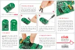
2. Soldering the headers
3. Plugging the board in
Once you have soldered the headers your
board is ready to be placed into the desired
mikroBUS
™
socket. Make sure to align the cut
in the lower-right part of the board with the
markings on the silkscreen at the mikroBUS
™
socket. If all the pins are aligned
correctly, push the board all the
way into the socket.
Turn the board upward again. Make sure
to align the headers so that they are
perpendicular to the board, then solder the
pins carefully.
Turn the board upside down so that
the bottom side is facing you upwards.
Place shorter pins of the header into the
appropriate soldering pads.
Before using your click board
™
, make sure
to solder 1x8 male headers to both left and
right side of the board. Two 1x8 male headers
are included with the board in the package.
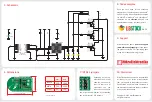
4. Essential features
To use TILT-n-SHAKE click as an accelerom-
eter, keep the enable pin (EN) pulled to logic
high. The 14-bit digital output has over ±8g
full-scale range with 1 mg/LSB sensitivity,
and a fast output time of about 700 micro-
seconds. As a tilt sensor, the MMA8491Q has
three detection outputs, one for each axis:
Xout, Yout and Zout. Three onboard LEDs will
also signal the tilt orientation.
1
TILT-n-SHAKE click carries Freescale’s
MMA8491Q
IC. It’s a multifunctional 3-axis
digital accelerometer that can also be
configured as a 45-degree Tilt sensor. As
an accelerometer, it communicates with the
target MCU through mikroBUS
™
I
2
C pins (SCL,
SDA). When configured as a Tilt sensor, the
click board needs only one output pin — INT
(interrupt). TILT-n-SHAKE click is designed
to use a 3.3V power supply only.
1. Introduction
TILTnSHAKE click manual
ver 1.00
0100000081266
click
BOARD
™
www.mikroe.com
TILT-n-SHAKE
click


