2
3
2. Soldering the headers
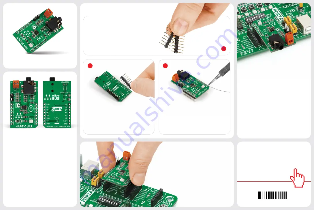
3. Plugging the board in
Once you have soldered the headers your
board is ready to be placed into the desired
mikroBUS
™
socket. Make sure to align the cut
in the lower-right part of the board with the
markings on the silkscreen at the mikroBUS
™
socket. If all the pins are aligned
correctly, push the board all the
way into the socket.
Turn the board upward again. Make sure
to align the headers so that they are
perpendicular to the board, then solder the
pins carefully.
Turn the board upside down so that
the bottom side is facing you upwards.
Place shorter pins of the header into the
appropriate soldering pads.
Before using your click board
™
, make sure
to solder 1x8 male headers to both left and
right side of the board. Two 1x8 male headers
are included with the board in the package.
4. Essential features
The DRV2605 IC integrates an extensive
library with over 100 haptic effects.
These include audio-to-vibe features,
which generate vibrations from the lower
frequency range of the audio input (licensed
version of TouchSense® 2200 effects from
Immersion™). A real-time playback mode
allows the host MCU to bypass the effects
and send waveforms to the motor directly
through I2C pins. This board is ideal for
enhancing User Interface designs with the
addition of tactile feedback. Applications
include touch-enabled devices, remote
controls as well as wearables.
1
Haptic click carries DRV2605, a Haptic
Driver for ERM and LRA vibration motors
(acronyms stand for Eccentric Rotating
Mass and Linear Resonant Actuator,
respectively). The board also carries screw
terminals for connecting said motors, as
well as an audio interface (3.5mm jack).
Haptic click communicates with the target
MCU through mikroBUS™ I2C (SCL, SDA),
EN (in place of CS) and PWM pins. The
board is designed to use either a 3.3V or
5V power supply.
1. Introduction
HAPTIC click Manual v100
0100000090022
click
BOARDS
™
www.mikroe.com
HAPTIC
click
HAPTIC click Manual v101


