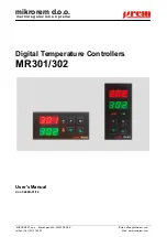
Digital Temperature Controllers MR301/302
2/12
"MIKROREM", Braće Spasić 4A, ČAČAK
Tel/fax: +381 (32) 370 500
Table of contents
1.
Features................................................................................................................................................... 3
2.
Front-panel description and button functions .......................................................................................... 3
3.
Access levels ........................................................................................................................................... 3
4.
Layout of menus and parameters ............................................................................................................ 4
5.
Parameter setting .................................................................................................................................... 5
5.1.
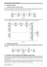
Setting the Set Point (SP parameter) ............................................................................................... 5
5.2.
Setting other parameters .................................................................................................................. 5
6.
Overview of some important configuration parameters ........................................................................... 5
7.
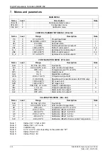
Menus and parametars ............................................................................................................................ 6
7.1.
Control parameters ........................................................................................................................... 7
7.2.
Configuration parameters ................................................................................................................. 7
7.3.
Calibration parameters ..................................................................................................................... 9
8.
Error messages ....................................................................................................................................... 9
9.
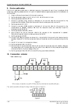
Device calibration .................................................................................................................................. 10
10.
Connection scheme ............................................................................................................................... 10
11.
Specifications ........................................................................................................................................ 11
11.1.
Possible sensors and measuring ranges ....................................................................................... 11
11.2.
Electrical specifications .................................................................................................................. 11
11.3.
Dimensions ..................................................................................................................................... 11
11.4.
Ordering information ....................................................................................................................... 11
12.
Notes ..................................................................................................................................................... 12

