background image

Assembling

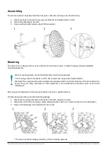
The device needs to be assembled from four parts, LHG dish, two legs and, the main body.

1. Attach two legs to the main body, legs are different and marked with L and R.
2. Attach the assembly to the dish.
3. Secure with provided screws using PH2 screwdriver.

Mounting

The LHG XL ac is designed to be used outdoors and mounted on pole or mast. Package includes adjustable 
mounting assembly.

When mounting, please ensure that cable feed is pointing downwards.
The IP rating scale of this device is IP54. We recommend using Cat6 shielded cables.
Warning! This equipment should be installed and operated with a minimum distance of 20 cm between the
device   and   your   body.   Operation   of   this   equipment   in   the   residential  environment   could   cause   radio
interference.

Mounting and configuration of this device should be done by a qualified person.

The Mounting assembly is provided with the package.

1. Attach the mounting assembly to the back of the dish using four screws.
2. Attach the unit to the pole using U clamp placing washers and nuts in order as shown on the illustration.
3. Align unit accordingly to the signal and secure nuts.

* The device should be always placed by UP arrow facing upwards.

See mikrotik.com/products for the latest version of this document.

Page 2, Document #51437 Modified on: 16.AUG.2019

Summary of Contents for LHG XL 52 ac

Page 1: ...er PoE 802 3af at 12 57 Vdc 12 57 Vdc The power consumption 8 W Connecting to a PoE Adapter 1 Connect the Ethernet cable from the device to the PoE DATA port of the PoE adapter 2 Connect an Ethernet cable from your local network LAN to the PoE adapter 3 Connect the power cord to the adapter and then plug the power cord into a power outlet Radio module Information Max Output Power EIRP 16 3 dBm 241...

Page 2: ...ng This equipment should be installed and operated with a minimum distance of 20 cm between the device and your body Operation of this equipment in the residential environment could cause radio interference Mounting and configuration of this device should be done by a qualified person The Mounting assembly is provided with the package 1 Attach the mounting assembly to the back of the dish using fo...

Page 3: ...reless strength blink the LEDs on interface traffic activity and many other options For further information please visit https wiki mikrotik com wiki Manual System LEDS Default factory configuration for this device Green LED the fourth level of signal strength Green LED the third level of signal strength Green LED the second level of signal strength Green LED the first level of signal strength Sol...

Page 4: ...GHz 802 11a n ac protocol Reset button The reset button has three functions Hold this button during boot time until LED light starts flashing release the button to reset RouterOS configuration total 5 seconds Keep holding for 5 more seconds LED turns solid release now to turn on CAP mode The device will now look for a CAPsMAN server total 10 seconds Or Keep holding the button for 5 more seconds un...

Page 5: ...trolled environment This equipment should be installed and operated with a minimum distance of 20 cm between the radiator and any part of your body Usage of device Indoor Outdoor Industry Canada IC 7442A LHG5ACD2HPD This device complies with Industry Canada licence exempt RSS standard s Operation is subject to the following two conditions 1 this device may not cause interference and 2 this device ...

Reviews: