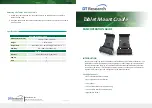
background image

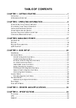
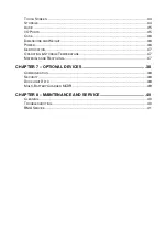
TABLE OF CONTENTS 

CHAPTER 1 - GETTING STARTED .............................................................. 1


U

NPACKING

 .................................................................................................................. 1


A

PPEARANCE 

O

VERVIEW

 ............................................................................................... 2


CHAPTER2 - OPERATING INFORMATION ................................................. 6


S

TART 

U

SING 

Y

OUR 

T

ABLET 

C

OMPUTER

 ......................................................................... 6


S

TOP 

U

SING 

Y

OUR 

T

ABLET 

C

OMPUTER

 .......................................................................... 7


I

NSTALLING 

O

PERATING 

S

YSTEM

 .................................................................................... 8


U

SING 

I

NDICATORS AND 

K

EYPAD

 .................................................................................... 8


S

ETTING 

F

UNCTION FOR 

B

UTTONS 

A1~A3 .................................................................... 10


O

PERATING 

W

IRELESS 

D

EVICES

 ................................................................................... 12


CHAPTER3- MANAGING POWER ............................................................. 17


AC


A

DAPTER

 .............................................................................................................. 17


B

ATTERY

 .................................................................................................................... 18


B

ATTERY 

R

ECALIBRATION

 ............................................................................................ 20


ACPI


S

UPPORT

 .......................................................................................................... 21


CHAPTER 4 - BIOS SETUP ........................................................................ 22


M

AIN 

M

ENU

 ................................................................................................................ 22


A

DVANCED 

M

ENU

 ........................................................................................................ 23


PCH-FW Configuration Sub-Menu...................................................................................... 24 
Trusted Computing Sub-Menu ........................................................................................... 24 
RF Device Control Configuration Sub-Menu ...................................................................... 25 
AC In Boot Control Sub-Menu ............................................................................................ 25 
USB CHARGE Control Sub-Menu ........................................................................................ 26 
Battery Recalibration Sub-Menu ........................................................................................ 26 
IT8760 Super IO Configuration Sub-Menu ......................................................................... 27 
Network Stack Configuration Sub-Menu ........................................................................... 27 
CSM Configuration Sub-Menu ........................................................................................... 28 

C

HIPSET 

M

ENU

 ........................................................................................................... 29


PCH-IO Configuration Sub-Menu ....................................................................................... 29 

S

ECURITY 

M

ENU

 ......................................................................................................... 30


HDD Security Configuration Sub-Menu ............................................................................. 30 

B

OOT 

M

ENU

 ............................................................................................................... 32


S

AVE 

&


E

XIT 

M

ENU

 ..................................................................................................... 32


CHAPTER 5 – DRIVERS AND APPLICATIONS ......................................... 33


CHAPTER 6 – SPECIFICATIONS ............................................................... 34


P

LATFORM

 .................................................................................................................. 34


CPU .......................................................................................................................... 34


M

EMORY

 .................................................................................................................... 34
 

Summary of Contents for DT13

Page 1: ...TABLET COMPUTER DT13 USER S GUIDE BC ...

Page 2: ... information MilDef Crete Inc makes no representations or warranties either expressed or implied with respect to the contents hereof and specifically disclaims any warranties for the correctness of this book nor any license grant of MilDef Crete Inc s patents or intellectual properties MilDef Crete Inc assumes no liability for customer s loss or damage caused by using this document Trademarks Trad...

Page 3: ...he equipment The manufacturer is not responsible for any radio or television interference caused by unauthorized modification of this device or the substitution of the connecting cables and equipment other than manufacturer specified It is the responsibility of the user to correct any interference caused by such unauthorized modification substitution or attachment Manufacturer and its authorized r...

Page 4: ...adio communications However there is no guarantee that interference will not occur in a particular installation If this equipment does cause harmful interference to radio or television reception which can be determined by turning the equipment off and on the user is encouraged to try to correct the interference by one or more of the following measures Reorient or relocate the receiving antenna Inc...

Page 5: ...95 EC the Amendment Directive 93 68 EEC and the procedures given in European Council Directive 99 5 EC and 2004 108 EC The equipment was passed and the equipment test was performed according to the following European standards EN 300 328 V1 8 1 2012 EN 301 893 V1 7 1 2012 EN 301 489 1 V1 9 2 2011 EN 301 489 3 V1 4 1 2002 EN 301 489 17 V2 2 1 2012 EN62311 2008 EN300440 1 V1 6 1 2010 EN300440 2 V1 4...

Page 6: ...ing product safety Please do not neglect the importance of this mechanism If you are unable to access a compatible outlet please hire a qualified electrician to install a compatible outlet for you When unplugging the AC power cord please make sure to disconnect the cord by pulling from the plug head instead of pulling from the wire to prevent wire damage Make sure the power outlet and any other ex...

Page 7: ...ease dispose of damaged battery promptly and carefully Explosion or leakage may occur if the battery is exposed to fire improperly handled or discarded If the battery will not be used for a long period please charge the battery to 50 and remove AC adapter If the battery is stored in a system it should be recharged to 50 every 3 months If the battery is stored solely it should be recharged every 6 ...

Page 8: ...s because the internal temperature of the battery does not equal to the ambient temperature Battery Disposal Caution The product that you have purchased contains a rechargeable battery The battery is recyclable At the end of its service life under various state and local laws it may be illegal to dispose of this battery into the municipal waste stream Check with your local solid waste officials fo...

Page 9: ...nto the eco system and to minimize the pressure on the natural environment you are encouraged to reuse or recycle most of the materials in a safe way after the product s service life For more information on collection reuse and recycle of materials please consult local or regional waste administrations for more information You can also contact your dealer for more information on the environmental ...

Page 10: ...21 CHAPTER 4 BIOS SETUP 22 MAIN MENU 22 ADVANCED MENU 23 PCH FW Configuration Sub Menu 24 Trusted Computing Sub Menu 24 RF Device Control Configuration Sub Menu 25 AC In Boot Control Sub Menu 25 USB CHARGE Control Sub Menu 26 Battery Recalibration Sub Menu 26 IT8760 Super IO Configuration Sub Menu 27 Network Stack Configuration Sub Menu 27 CSM Configuration Sub Menu 28 CHIPSET MENU 29 PCH IO Confi...

Page 11: ... 36 POWER 36 CERTIFICATION 37 OPERATING STORAGE TEMPERATURE 37 MATERIALS AND RECYCLING 37 CHAPTER 7 OPTIONAL DEVICES 38 COMMUNICATION 38 SECURITY 38 DOCKLIGHT DL10 38 MULTI BATTERY CHARGER MCDR 39 CHAPTER 8 MAINTENANCE AND SERVICE 40 CLEANING 40 TROUBLESHOOTING 40 RMA SERVICE 41 ...

Page 12: ... Getting Started Chapter 1 Getting Started Unpacking The following components come with your computer If anything is missing or damaged please notify the dealer immediately Tablet omputer unit AC Adapter Quick Guide ...

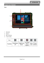
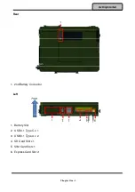
Page 13: ...Chapter One 2 Getting Started Appearance Overview Front 1 Keyboard 2 Buttons 3 LED Indicators 4 Touch Screen ...

Page 14: ...Chapter One 3 Getting Started Rear 1 2nd Battery Connector Left 1 Battery Slot 2 USB 3 1 Type C x 1 3 USB 3 1 Type A x 2 4 SD Card Slot x1 5 SIM Card Slot x1 6 Express Card Slot x1 ...

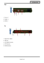
Page 15: ...Chapter One 4 Getting Started Right 1 DC In x 1 2 GLAN x 1 3 DB15 x 1 Top 1 Night Vision Switch 2 SSD slot 3 GPS SMA Connector 4 GPS Antenna 5 WLAN Antenna ...

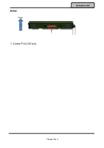
Page 16: ...Chapter One 5 Getting Started Bottom 1 Docket Port 120 pin ...

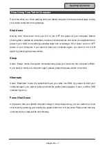
Page 17: ... operating procedure to start using your tablet computer After turning on the power of your tablet computer it will start with the Operating System OS installed Boot Up When you turn on the power your computer will start to load the OS into the system memory This start up procedure is called boot up Power On Self Test POST Each time your computer is turned on the BIOS will automatically perform a ...

Page 18: ...t to start your computer again you need to turn it ON again by pressing the power button Sleep Under Sleep mode the system will temporarily save your work into the computer s RAM If you want to start your computer again please press the power button to resume Hibernate Under Hibernate mode the system will save your work into SSD If you want to start your computer again you need to press and hold t...

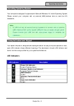
Page 19: ...dicator shows different meanings The description of each LED indicator and button functions are provided for your operational reference LED Indicators LED Indicator Description Power S3 Indicator Green Flashing Green Charger Battery Low Indicator Orange Flashing Orange SSD Indicator Green Wireless Function Indicator Blue Caps Lock Indicator Green Note A USB hub may be required during installation ...

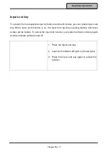
Page 20: ...When Input Lock function is on the input from devices including buttons and touch screen will be locked To cancel the input lock function just press the Input Lock key again and the indicator will be turned off 1 Press the Input Lock key 2 Input Lock Indicator will light on Green light 3 Press the Input Lock key again to cancel the function ...

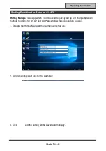
Page 21: ...an app which could be used to quickly set up and change between multiple functions for A1 A2 and A3 Please follow these procedure to use it 1 Operate the Hotkey Manager then a menu will show up 2 Scroll down to select function for each key 3 Click and the setting will be saved automatically ...

Page 22: ...ERROR ioerror OFFENDING COMMAND image STACK ...

Reviews: