(Refer to previous page)
Keep all hoses away from any areas where heat may be considered too extreme (such as exhaust manifold or turbo). Lines should not to be
allowed to rub on any abrasive or vibrating surfaces. In some applications, 90° fittings on the solenoid valve are necessary to make hose
mounting more flexible. After plumbing has been laid out on vehicle, install O ring fittings supplied to valve. Torque tight. Do not over tighten
any fittings. Install O ring fittings on winch motor. Torque tight. Connect hose number two to port number two on the valve assembly. Attach
the other end of hose number 2 to any port on winch. Connect hose number four to port number four on valve assembly and attach the other
end of number four to the other port on winch. Torque both hoses (both sides) ¼ turn past finger tight.
Disconnect original (OEM) high pressure line from the power steering pump to the steering gearbox. If your truck has hydroboost brakes, you
need to remove the high pressure line from the hydroboost to the steering box. NOTE: Low pressure line will normally have a hose clamp (Fig. 3).
NOTE:
Make sure and reuse any 0 rings or seals from OEM tube fittings
NOTE:
If the hand control unit is working backwards, simply reverse the black and white wire connectors on the valve assembly
CAUTION:
Fluid will be lost from the system.
Fig. 3
2121 Blount Road Pompano Beach, FL 33069 MileMarker.com 1.800.886.8647
PAGE 7
PLUMBING CONNECTIONS
Pump
Pump
pulley
Cooler
to pump
return
hose
Cooler
tube
Gear to cooler
return hose
Master cylinder
assembly
Hydroboost
Hydroboost
to pump
return hose
Pump to
hydroboost
pressure
hose
Power steering
gear assembly
Hydroboost
to gear
pressure
hose
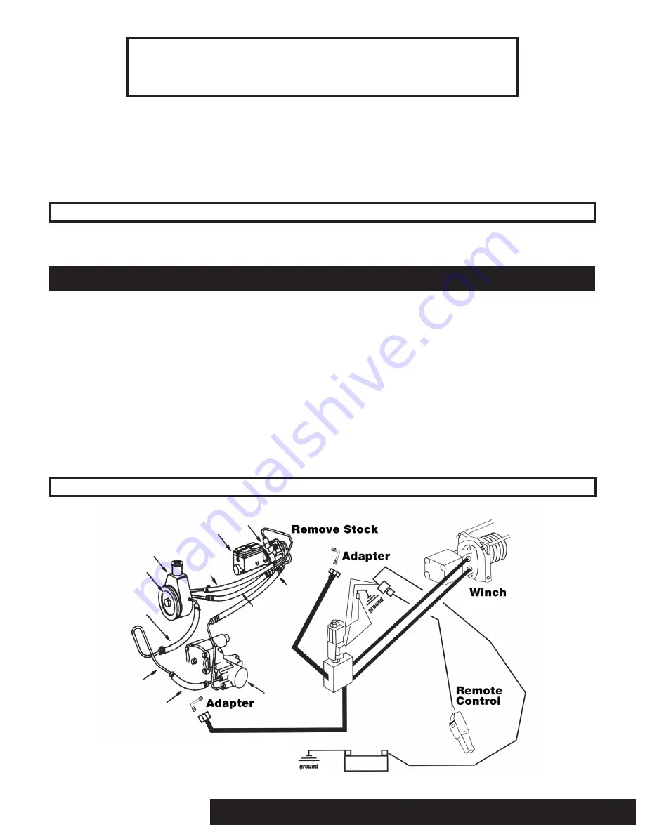
(Refer to Fig. 2 on previous page)
Attach any O ring or seal from vehicle’s original tube fitting to tube fitting #3. Connect tube fitting #3 to power steering pump. Torque to
vehicle factory specifications. Connect hose #3 to tube fitting #3. Torque ¼ turn past finger tight. Attach other end of hose #3 to port #3 on
solenoid valve. Torque ¼ turn past finger tight. Attach any O ring or seal from vehicle’s original tube fitting to tube fitting #1. Connect tube
fitting #1 to steering gearbox. Torque to vehicle factory specification. Attach hose #1 to tube fitting #1. Torque ¼ turn past finger tight.
Connect the other end of hose #1 on solenoid valve. Torque ¼ turn past finger tight.
If your application is supplied with an added cooler, remove (OEM) low pressure line from reservoir. Attach hose #5 to existing return line
using male to male coupler and hose clamps supplied. Tighten hose clamps. Connect the other side of hose #5 to cooler supplied with hose
clamp. Tighten hose clamp. Attach hose #6 to cooler and reservoir with hose clamps. Tighten hose clamps. Check fluid level. Replace lost
fluid to system. System will need to be purged. Lift pin on free spool release on winch. Manually pull approximately 10 feet of cable off winch
drum. Lock free spool pin back down. Add fluid until full. Start engine. Power winch cable out five feet. Shut off engine. Check fluid level. Add
fluid until full if necessary. Start engine. Power winch cable into desired position. Turn the vehicle’s front wheels from lock to lock position five
times (all the way to the right and then all the way to the left). This will aid in bleeding out any air that may have gotten into the system.


